


20
OPTIMIZER
a notch across the audio spectrum. A further creative use is
to create a pseudo stereo image from a mono signal by split-
ting the signal and applying different notches to each of the
two channels. If these two channels are then panned left and
right in the final mix, it creates an illusion of space. The
position, number and width of the notches must be fine
tuned by ear.
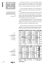
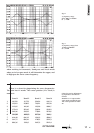
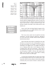
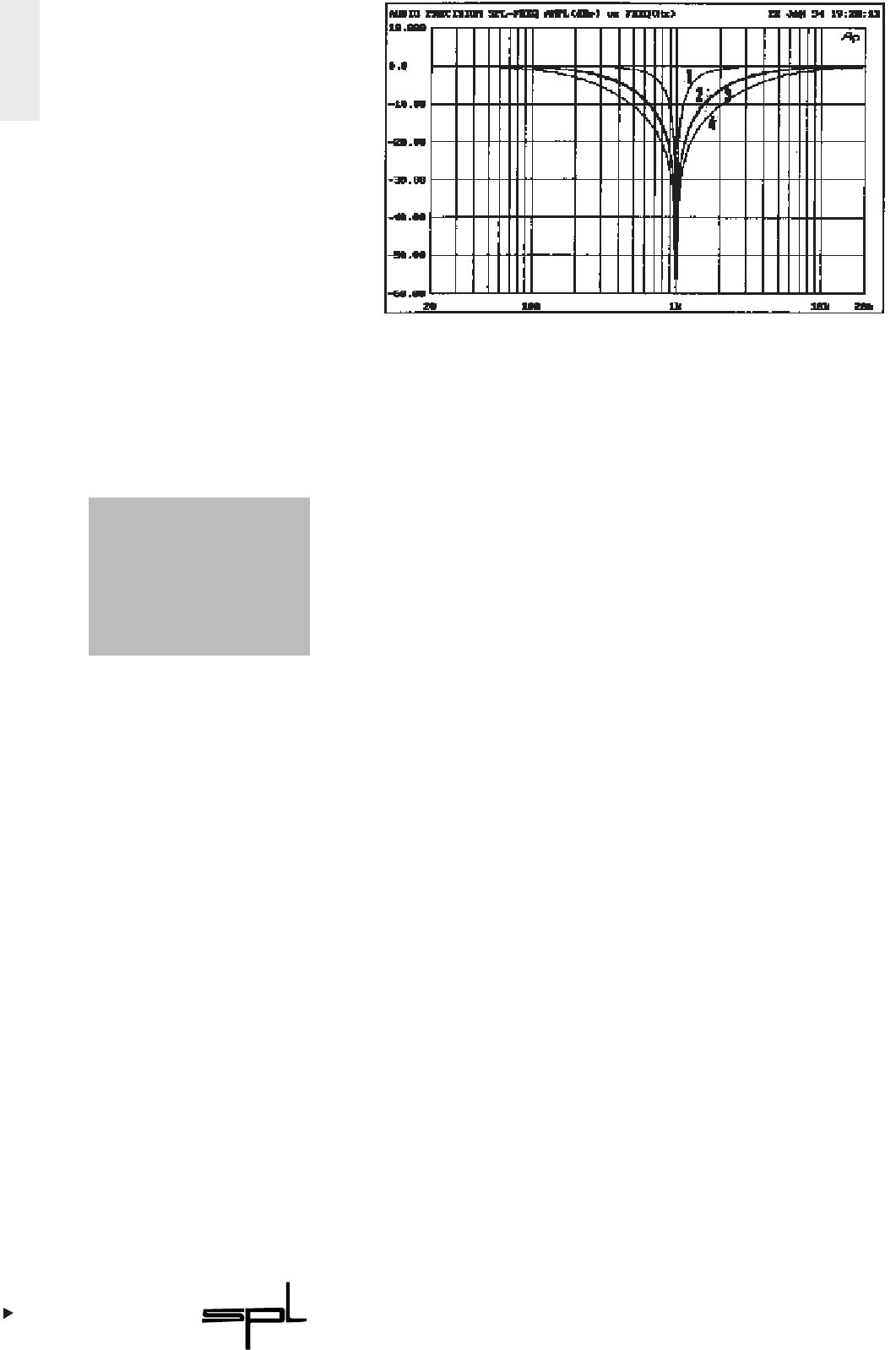
Curves 2 and 3 show an alomst identical response in Fig.
11. Nevertheless there is an audible difference that is much
greater than shown in the graph.
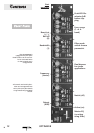
The 4-way rotary switch sets the equalizer function
(Parametric, Low-pass, High-pass, Band-pass), although if
you select Notch this overrides whatever other equalizer
mode has been selected.
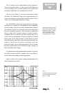
When using these three modes you should be aware that
the filters are connected in series, and depending on the fil-
ter types and settings, it is possible to set up a situation
where there is no output at all. For example, if one filter is
set as a High-pass filter with a cut-off frequency of 1kHz,
everything below 1kHz will be attenuated. If this signal is
now fed into the next stage, set as a Low-pass filter, with a
cut-off frequency of 500Hz, it will pass only signals below
500Hz. As the first filter’s output contains little or nothing
below 1kHz the result is very little signal.
For this reason, Band-pass filters are often used on their
own while High-pass and Low-pass are usually used as a pair
to provide control over the extremes of the audio spectrum.
Conversely, they can be used to ‘bracket’ a narrower section
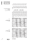
Fig. 11:
Notch:
Curve 1: Q = 1,5;
Roll-Off = steep
Curve 2: Q = 0,2;
Roll-Off = steep
Curve 3: Q = 1,5;
Roll-Off = gentle
Curve 4: Q = 0,2;
Roll-Off = gentle
CC
OONNTTRROOLLSS
PP
AARRAAMMEETTRRIICC
,,
HH
IIGGHHPPAASSSS
,,
BB
AANNDDPPAASSSS
,,
LL
OOWWPPAASSSS