


7
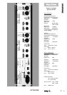
OPTIMIZER
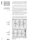
tion as each filter is added to the signal path. The Optimizer
overcomes this fault by using controllable all active output
stages resulting in a significantly improved phase response,
even when all four filters are linked up. The Output control
allows level adjustments to compensate for level changes due
to dramatic boost or cut adjustments.
The Optimizer is designed for standard 19” rack moun-
ting and occupies 2U of rack space. Avoid mounting the unit
directly above power amplifiers or power supplies that radia-
te significant amounts of heat and always connect the mains
earth to the unit. Fibre or plastic washers may be used to pre-
vent the front panel becoming marked by the mounting
bolts. Care must be taken when rack mounting the unit to
support the rear of the case, especially in mobile systems.
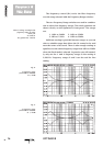
The Optimizer has connectors for unbalanced as well
balanced operation.
The XLR inputs and outputs are electronically balanced
on conventionally wired XLRs (pin 1 screen, pin 2 hot and
pin 3 cold). Unbalanced inputs and outputs are also availa-
ble on mono, quarter-inch jacks.
The signal connected to the jacks will always be prefer-
red. A connection set-up with XLR´s and jacks can remain
connected. Unplugging the jacks will select the XLRs as pri-
mary inputs.
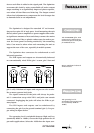
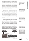
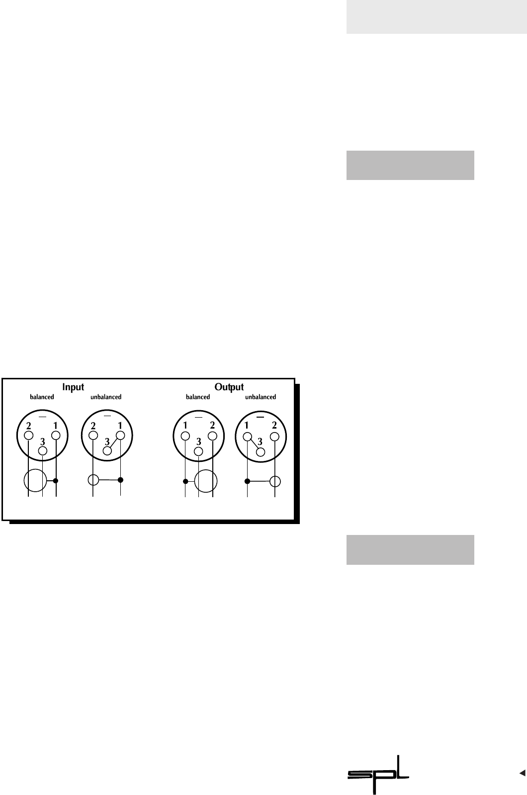
The XLR inputs and outputs can be unbalanced by
connecting the pin 3 to the ground terminal (pin 1). For pro-
per wiring see figure below.
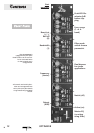
The operating level is switchable between High and Low
(nominally 0dBu or -10dBv). Choose the High position for all
pro-audio applications. Select the -10dB when the input sour-
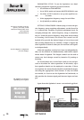
The OPTIMIZER offers XLR
connectors for balanced ope-
ration and quarter-inch jacks
for unbalanced use.
How to unbalance balanced
XLR connetors.
The operating level is
switchable between High and
Low (nominally 0dBu or -
10dBv)
II
NNSSTTAALLLLAATTIIOONN
CC
OONNNNEECCTTOORRSS
OO
PPEERRAATTIINNGG
LL
EEVVEELL