


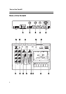


Parts of the Porta02
11
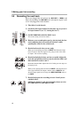
clockwise to
MIC
for any channel which
is recording a microphone.
Instruments such as electric guitars pro-
duce a signal which is between
MIC
and
LINE
levels and the
TRIM
control should
therefore be somewhere between fully
clockwise and fully counter-clockwise.
See 3.3, “Setting the level” for full details
of how to adjust the
TRIM
controls for dif-
ferent input sources.
[9] POWER indicator
This yellow light is lit when the Porta02
is connected to the power supply and
switched on.
[10] Tape counter and reset
button
The tape counter allows you to note dif-
ferent parts of the tape and locate to
them. Press the reset button to reset the
counter to “000” at any time (we suggest
that you only do this at the beginning of a
recording).
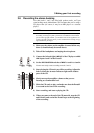
[11] OUTPUT LEVEL controls
These controls change the levels of the
four tape tracks in the
LINE OUT
and
PHONES
outputs. When one of these con-
trols is turned fully counter-clockwise,
the tape track corresponding to that con-
trol will not be heard in the
LINE OUT
and
PHONES
outputs.
[12] OUTPUT PAN controls
These controls change the position of the
four tape tracks in the stereo
LINE OUT
and
PHONES
outputs. When one of these
controls is turned fully counter-clock-
wise, the sound of the corresponding tape
track will appear to come from the left,
and when turned fully clockwise, it will
appear to come from the right. When in
the center position, the output will appear
equally from both the left and right.
When the
PHONES MONO
switch is
pressed, these controls will have no effect
on the output from the
PHONES
jack.
[13] REC FUNCTION switches
(1 and 2)
These switches control where the signals
coming into the
MIC/LINE
jacks will be
recorded. For both switches 1 and 2, the
center position is marked as
SAFE
. When
a switch is in this position, no signal will
be recorded on tape. However, you can
still listen to the signals coming into the
MIC/LINE
jacks and view the levels on the
meters.
When set to a number (
1
or
3
for channel
1, or
2
or
4
for channel 2), the signals
input to the channel will be recorded on
the track whose number has been set on
the switch. This is called “assigning” or
“routing” channels to tracks.
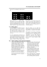
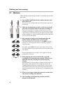
[14] Channel meters (1 and 2)
Each channel has a set of four LED indi-
cators which show the level of the signals
sent to the
LINE OUT L
and
R
jacks.
Exactly what is metered depends on the
REC FUNCTION switch settings, but gen-
erally, they display the signals at the
MIC/
LINE IN
jacks, and when the input chan-
nels are set to
SAFE, the meters show the
off-tape signals, whose levels and pan
positions are set using the
OUTPUT
LEVEL
and PAN controls.
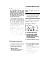
The best level for any input signal is
when an averagely loud part of the signal
lights the red
0 indicator, and the +6 indi-
cator (also red) is only lit by the loudest
parts of the signal. See 3.3, “Setting the
level” for details of how this should be set
up.
[15] Channel faders (1 and 2)
These faders are used to adjust the level
of the signals coming into the
MIC/LINE