Getting Started
80E00 Electrical Sampling Modules User Manual
3
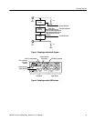
Sampler
Sampler
Strobe
Generator
Strobe drive
50 Ω
From main instrument
50 Ω
Note: the 80E01and 80E06 are
single channel modules with a
dedicated strobe drive and
generator.
To main instrument
To main instrument
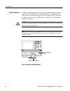
Figure 1: Sam pling module block diagram
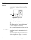
TDR on indicator
light (red)
(80E04)
Signal connector
Left channel
Right channel
Hold-down screw
SELECT channel button
TEKPROBE connector
Channel indicator
light (yellow)
Figure 2: Sam pling module, 80E04 shown


