


18-CD22D1-8 13
Installer’s Guide
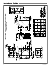
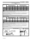
TABLE 6
MINIMUM CLEARANCE FROM COMBUSTIBLE MATERIALS FOR
UPFLOW/HORIZONTAL AND DOWNFLOW/ HORIZONTAL FURNACES
UNIT LOCATION
FURNACE SURFACE
VERTICAL
CLOSET
HORIZONTAL
CLOSET
HORIZONTAL
ALCOVE / ATTIC
SIDES 0" 1" 0"
BACK 0" 3" 6"
TOP 1" 1" 1"
FRONT 3" 3" 18"
VENT 0" 0" 0"
NOTE
: CLEARANCE REQUIRED AT TOP OF PLENUM IS 1"
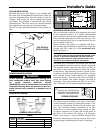
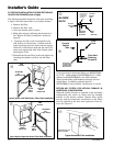
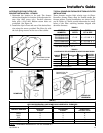
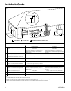
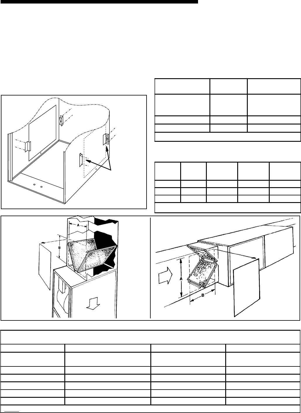
ALTERNATE UPFLOW FILTER CLIP/
BRACKET INSTALLATION - KIT09224
1. Determine the location to be used. The furnace
cabinet has dimples for location of the alternate fur-
nace clips (Side return only). Pre-drill clearance
holes with a 3/16" drill. Bottom return holes are
pre-drilled. See Figure 18.
2. Install the clips in front and rear of the desired loca-
tion using the screws provided. The filter clip with
the leaf spring mounts in the rear of the cabinet.
REAR
SIDE
CUT-OUT
ALTERNATE FILTER
CLIPS LOCATION
i
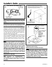
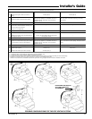
Airflow
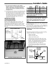
DOWNFLOW/
HORIZONTAL
DOWNFLOW
Airflow
o
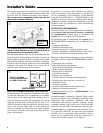
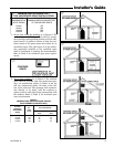
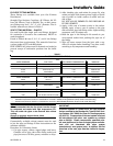
TYPICAL DOWNFLOW FURNACE RETURN AIR FILTER
INSTALLATIONS
These furnaces require high velocity type air filters.
Downflow furnace filters must be located outside the
furnace cabinet. Typical installations are shown in Fig-
ure 19. Tables 4, 5 and 6 provide information for instal-
lation of the filter retaining brackets shipped with
downflow furnaces.
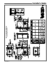
TABLE 4
MODELS
NUMBERS
CABINET
WIDTH
FILTER
QTY & SIZE
*DX1B040A9H21B
*DX1B060A9H31B
*DX1B080A9H31B
17-1/2" 2 - 14" X 20" X 1"
*DX1C100A9H41B 21" 2 - 16" X 20" X 1"
*DX1D120A9H51B 24-1/2" 2 - 16" X 20" X 1"
*First letter may be "A" or "T"
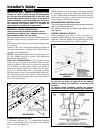
TABLE 5
LOCATING FILTER RETAINER BRACKETS IN DUCTWORK
CABINET
WIDTH
RETURN
DUCT
WIDTH
DIMENSION
"A"
DIMENSION
"B"
FILTER
BRACKET
LOCATION*
17-1/2" 16-1/4" 15" 14" 14-3/8"
21" 19-3/4" 19-1/2" 14" 13-1/8"
24-1/2" 23-1/4" 22" 14" 13-5/8"
* LOCATION DIMENSION IS FROM END OF DUCT AGAINST THE FURNACE TO THE
SCREW HOLES FOR THE BRACKET.
Optional door kit
BAYFLTR206