


18-CD22D1-8 3
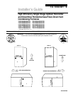
Installer’s Guide
INSTALLATION INSTRUCTIONS
General Installation Instructions 3
Location and Clearances 4
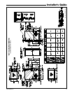
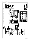
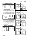
Outline Drawings 5
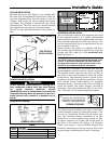
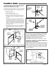
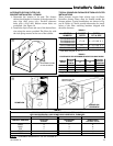
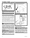
Upflow Installation 7
Downflow Installation 7
Horizontal Installation 7
Air For Combustion and Ventilation 8
Duct Connections 10
Return Air Filters 11
General Venting Instructions 14
Venting Material 15
Venting Tables 15
Horizontal Venting 16
Venting Through The Wall 20
Venting Through The Roof 20
Downward Venting 22
Venting Through a Masonry Chimney 22
Condensate Drain Instructions 25
Electrical Connections 27
Field Wiring Diagrams 27
Gas Piping 29
Combustion Input Checks 31
Start Up and Adjustment 33
Preliminary Inspections 33
Lighting Instructions 34
Sequence Of Operation 34
Control And Safety Switch Adjustments 34
Airflow Adjustment 35
Conditions Affecting Furnace Operation 35
IFC Error Flash Code 37
GENERAL INSTALLATION INSTRUCTIONS
The manufacturer assumes no responsibility for equip-
ment installed in violation of any code or regulation.
It is recommended that Manual J of the Air Condition-
ing Contractors Association (ACCA) or A.R.I. 230 be fol-
lowed in estimating heating requirements. When esti-
mating heating requirements for installation at alti-
tudes above 2000 ft., remember the gas input may need
to be reduced (See High Altitude Installation).
Material in this shipment has been inspected at
the factory and released to the transportation
agency without known damage. Inspect exterior
of carton for evidence of rough handling in ship-
ment. Unpack carefully after moving equipment
to approximate location. If damage to contents is
found, report the damage immediately to the de-
livering agency.
Codes and local utility requirements governing the
installation of gas fired equipment, wiring, plumbing,
and flue connections must be adhered to. In the ab-
sence of local codes, the installation must conform with
latest edition of the National Fuel Gas Code ANSI
Z223.1 • National Installation Code, CAN/CGA B149.1.
The latest code may be obtained from the American Gas
Association Laboratories, 400 N. Capitol St. NW,
Washington D.C. 20001.
1-800-699-9277 or www.aga.org
These furnaces have been classified as CATEGORY IV
furnaces in accordance with latest edition of ANSI
Z21.47 • CAN/ CGA 2.3 standards.
Contents
▲
WARNING
!
FIRE OR EXPLOSION HAZARD
Failure to follow the safety warnings exactly could re-
sult in serious injury, death or property damage.
Improper servicing could result in dangerous opera-
tion, serious injury, death, or property damage.
Safety signal words are used to designate a degree or level
of seriousness associated with a particular hazard. The
signal words for safety markings are WARNING and
CAUTION.
a. WARNING indicates a potentially hazardous situation
which, if not avoided, could result in death or serious
injury.
b. CAUTION indicates a potentially hazardous situation
which, if not avoided, may result in minor or moderate
injury. It is also used to alert against unsafe practices
and hazards involving only property damage.
Category IV furnaces operate with positive vent static
pressure and with a flue loss less than 17 percent.
These conditions require special venting systems, which
must be gas tight and water tight. These Category IV
Direct Vent furnaces are approved for installation in
Manufactured/Mobile housing when used with
BAYMFGH100A.