


18-CD22D1-8 11
Installer’s Guide
9. The horizontal installation of the upflow
furnace requires an external filter section. Do
NOT use the bottom return filter within the
furnace. Filter kits are available for horizon-
tal applications.
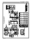
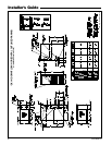
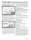
10. Connect duct work to furnace. See Outline Drawing
for supply and return duct size and location. Flex-
ible duct connectors are recommended to connect
both supply and return air ducts to the furnace. If
only the front of the furnace is accessible, it is
recommended that both supply and return air
plenums are removable.
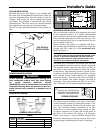
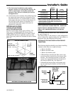
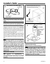
RETURN AIR FILTERS
TYPICAL UPFLOW RETURN
AIR FILTER INSTALLATIONS
furnaces require high velocity type air filters. The
filters may be installed within the furnace blower
compartment for UPFLOW furnaces in either a BOT-
TOM or SIDE (left side or right side) return air inlet.
Some filters may need to be trimmed for side or bottom
filter use.
UPFLOW FURNACE ONLY
*
SEE OUTLINE DRAWING
FRONT
of Furnace
LOCATING
NOTCHES PRO-
VIDED FOR SIDE
RETURN CUTOUT
0
CUT OUT
FOR SIDE
FILTER
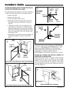
BOTTOM FILTER RACK INSTALLATION
Airflow
q
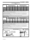
TABLE 3
MODELS
NUMBERS
CABINET
WIDTH
FILTER
QTY & SIZE
*UX1B040A9H21B
*UX1B060A9H31B
*UX1B080A9H31B
17-1/2" 1 - 17" X 25" X 1"
*UX1C100A9H41B 21" 1 - 20" X 25" X 1"
*UX1D120A9H51B 24-1/2" 1 - 24" X 25" X 1"
*First letter may be "A" or "T"
**NOTE: For upflow 5 ton airflow models where the airflow
requirement exceeds 1800 CFM - Modles will require return air
openings and filters on: (1) both sides, or (2) one side and the
bottom, or (3) just on the bottom
NOTE: For upflow 5 ton airflow models where the
airflow requirement exceeds 1800 CFM - Models will
require return air openings and filters on: (1) both
sides, or (2)1 side and the bottom, or (3) just the
bottom.
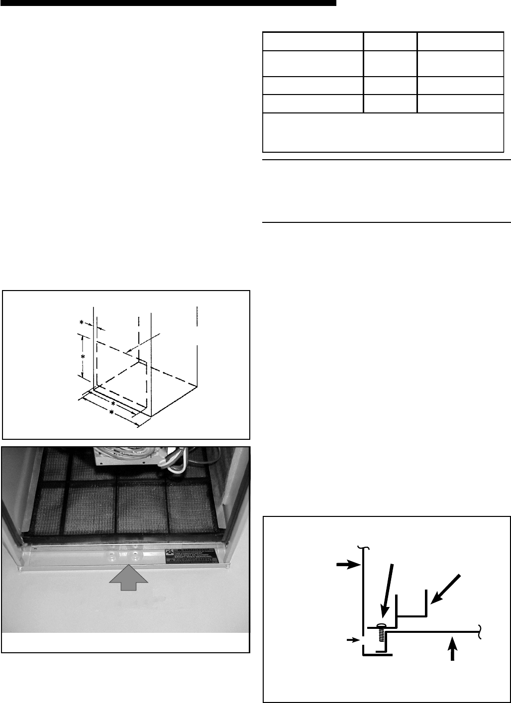
The furnace and the bottom filter rack installation can
be seen in Figure 11.
The furnace filter in the bottom or side configuration
can be removed by simply turning the two latches on
the blower door and tilting the door forward.
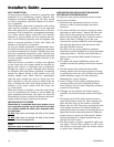
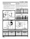
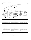
OPTIONAL FILTER RACK INSTALLATION FOR BOT-
TOM RETURN
The following checklist should be used when installing
a bottom return filter on an upflow furnace:
a. Remove the filter.
b. Remove the filter rack.
c. Remove the bottom panel.
e. With the filter removed, the filter rack is com-
pressed and then inserted into the bottom of the
furnace. The retaining screw/pin on each side
inserts into engagement holes at the bottom of
the furnace cabinet side. See Figure 12.
f. Reinstall the furnace filter in the bottom posi-
tion by inserting the chamfer end first into the
filter rack
Bottom Panel
Filter
Rack
Furnace
Cabinet
Side
Filter Rack
Retaining
Screw/Pin
Engagement Hole
For
Bottom Return
Filter Rack
Installation With
w