


26 18-CD22D1-8
Installer’s Guide
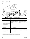
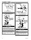
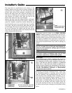
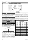
The trap must be repositioned to the exterior of the
cabinet. Remove the trap from its present location and
reposition the trap outside of the unit, through the long
circular hole, next to the secondary recuperative cell.
Remove the larger drain line (from the secondary cell)
and trim to fit between the secondary cell and the new
trap location. On upflow units, plug the hole in the
blower deck where the tube went through.
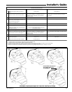
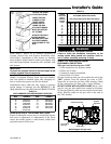
Remove the hose from the induced blower and reposi-
tion into the other drain tap of the inducer, which is lo-
cated 90° clockwise around the inducer. Move the cap
from that drain tap to the unused drain tap. On upflow
units, plug the hole in the blower deck where the tube
went through. This tube on downflow units will need to
be cut to fit between the inducer and the trap. On up-
flow units, this tube may need to be extended, using the
tubing shipped with the furnace.
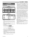
Connections must be made to an OPEN/ VENTED
DRAIN. Outdoor draining of the furnace and coil con-
densate is permissible if allowed by local codes. Caution
should be taken to prevent drains from freezing or caus-
ing slippery conditions that could lead to personal in-
jury. Excessive draining of condensate may cause satu-
rated ground conditions that may result in damage to
plants.
NOTE:
Use 1/2" or larger PVC or CPVC pipe and fittings as re-
quired for drain connections (fittings, pipe and solvent
cement not provided).
NOTE:
A corrosion resistant condensate pump must be used
if a pump is required for a specific drain system.
IMPORTANT:
The condensate drain should be installed with provisions to
prevent winter freeze-up of the condensate drain line. Fro-
zen condensate will block drains, resulting in furnace shut-
down. If the drain line cannot be installed in a conditioned
space, then UL listed heat tape should be applied as re-
quired to prevent freezing (per manufacturer’s instructions).
The heat tape should be rated at 5 or 6 watts per foot at
120 volts. Self-regulating (preferred) or thermostatically
controlled heat tape is required.
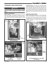
Evaporator and furnace condensate drain piping may
be manifolded together. A primary drain vent stack
must be installed and terminated below the outlet of
the secondary heat exchanger drain connection to pre-
vent water from damaging furnace controls if the pri-
mary drain outlet plugs up. Where the furnace is in-
stalled above a finished ceiling, the primary drain vent
stack must be installed such that overflow from the
vent stack opening will flow into an axillary drain pan
in order to prevent water damage to the finished ceiling
below.
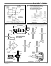
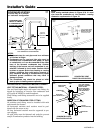
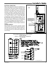
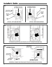
DOWNFLOW (VERTICAL)
Left
side
Use CPVC tubing from Trap outlet,
over burner box to cabinet exit
DOWNFLOW
(VERTICAL)
Right
side
Cut off curved end of
Inducer drain hose
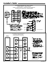
DOWNFLOW (HORIZONTAL)
%
$
^