


34 18-CD22D1-8
Installer’s Guide
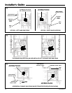
LIGHTING INSTRUCTIONS
▲
WARNING
!
DO NOT attempt to manually light the burner.
Failure to follow this warning could result in property
damage, personal injury or death.
Lighting instructions appear on each unit. Each instal-
lation must be checked out at the time of initial start up
to insure proper operation of all components. Check out
should include putting the unit through one complete
cycle as outlined below.
Turn on the main electrical supply and set the thermo-
stat above the indicated temperature. The ignitor will
automatically heat, then the gas valve is energized to
permit the flow of gas to the burners. After ignition and
flame is established, the flame control module monitors
the flame and supplies power to the gas valve until the
thermostat is satisfied.
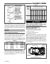
To shut off.
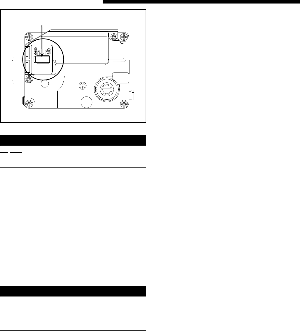
For complete shut-down: Flip the switch on the main
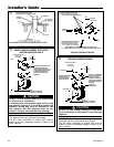
gas valve to the “OFF” position, (See Figure 53 & 54).
Disconnect the electrical supply to the unit.
▲
CAUTION
!
If this is done during the cold weather months, provi-
sions must be taken to prevent freeze-up of all water
pipes and water receptacles.
Failure to follow this warning could result in property
damage.
Whenever your house is to be vacant, arrange to have
someone inspect your house for proper temperature.
This is very important during freezing weather. If for
any reason your furnace should fail to operate damage
could result, such as frozen water pipes.
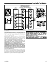
SEQUENCE OF OPERATION
Thermostat call for heat
R and W thermostat contacts close signaling the control
module to run its self-check routine. After the control
module has verified that the pressure switch contacts
are open and the limit switch(es) contacts are closed,
the draft blower will be energized.
As the induced draft blower comes up to speed, the
pressure switch contacts will close and the ignitor warm
up period will begin. The ignitor will heat for approxi-
mately 20 seconds, then the gas valve is energized to
permit gas flow to the burners. The flame sensor con-
firms that ignition has been achieved.
After the flame sensor confirms within a 4 second trial
period that ignition has been achieved, the delay to fan
ON period begins timing. After approximately 45 sec-
onds the indoor blower motor will be energized and con-
tinue to run during the heating cycle.
When the thermostat is satisfied, R and W thermostat
contacts open, the gas valve will close, the flames will
extinguish, and the induced draft blower will be de-en-
ergized. The indoor blower motor will continue to run
for the fan off period (Field selectable at 60, 100, 140 or
180 seconds), then be de-energized by the control mod-
ule.
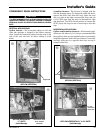
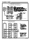
CONTROL AND SAFETY SWITCH ADJUSTMENTS
LIMIT SWITCH CHECK OUT
The limit switch is a safety device designed to close the
gas valve should the furnace become overheated. Since
proper operation of this switch is important to the
safety of the unit, it must be checked out on initial
start up by the installer.
To check for proper operation of the limit switches, set
the thermostat to a temperature higher than the indi-
cated temperature to bring on the gas valve. Restrict
the airflow by blocking the return air (disconnecting the
indoor blower may trip the inducer limit). When the
furnace reaches the maximum outlet temperature as
shown on the rating plate, the burners must shut off. If
they do not shut off after a reasonable time and over-
heating is evident, a faulty limit switch is probable and
the limit switch must be replaced. After checking the
operation of the limit control, be sure to remove the pa-
per or cardboard from the return air inlet. Refer to Ser-
vice Facts for additional instructions.
NOTE TO INSTALLER
Review the following warnings with the owner. Review
contents of USER’S INFORMATION MANUAL with the
owner.
On/O
ff
ff
Swi
Swit
ch
ch
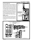
R
White-Rodgers 36F gas valve