6 VT1536A Isolated Digital Input/Output SCP
Recommended Signal Connections
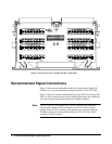
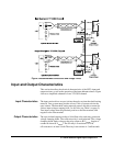
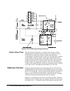
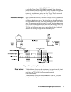
Figure 3 shows the recommended method of wiring isolated digital I/O
channels, as well as the maximum voltage limitations for the VT1536A.
Figure 3 shows the shields connected directly to the VT1415A/19A ground.
This is to limit potential noise on the isolated digital wiring from affecting
low-level analog channel wiring within the Terminal Module.
Note The VT1536A is a true isolated SCP. There is no electrical connection
between each channel's Hi/Lo terminals and VT1415A/19A's chassis
ground. However the G (analog guard) terminals are connected through
10
kOhm resistors to chassis ground within the VT1415A/19A. These
terminals are NOT isolated.
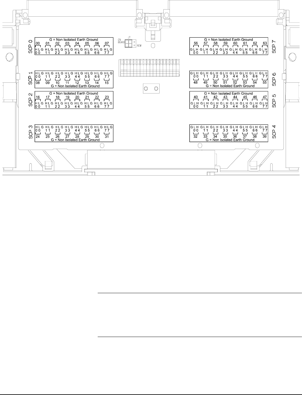
Figure 2 VT1415A/19A/22A Terminal Module Connections


