


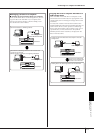
Using Your Instrument with
Other Devices
PSR-OR700 Owner’s Manual
181
MIDI Settings
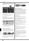
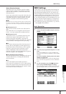
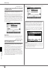
● Tx MONITOR
The dots corresponding to each channel (1-16) flash
briefly whenever any data is transmitted on the chan-
nel(s).
n
When different parts are assigned to the same transmit
channel
If the same transmit channel is assigned to several different parts,
the transmitted MIDI messages are merged to a single channel —
resulting in unexpected sounds and possible glitches in the con-
nected MIDI device.
n
About the protected Songs
Write-protected Songs cannot be transmitted even if the proper
Song channels 1–16 are set to be transmitted.
■ MIDI messages which can be transmitted or
received (recognized)
The following MIDI messages can be set on the TRANS-
MIT/RECEIVE display.
• Note (Note events).......................................page 164
• CC (CONTROL CHANGE) ..........................page 164
• PC (PROGRAM CHANGE)...........................page 164
• PB (Pitch Bend)............................................page 164
•AT (Aftertouch).............................................page 164
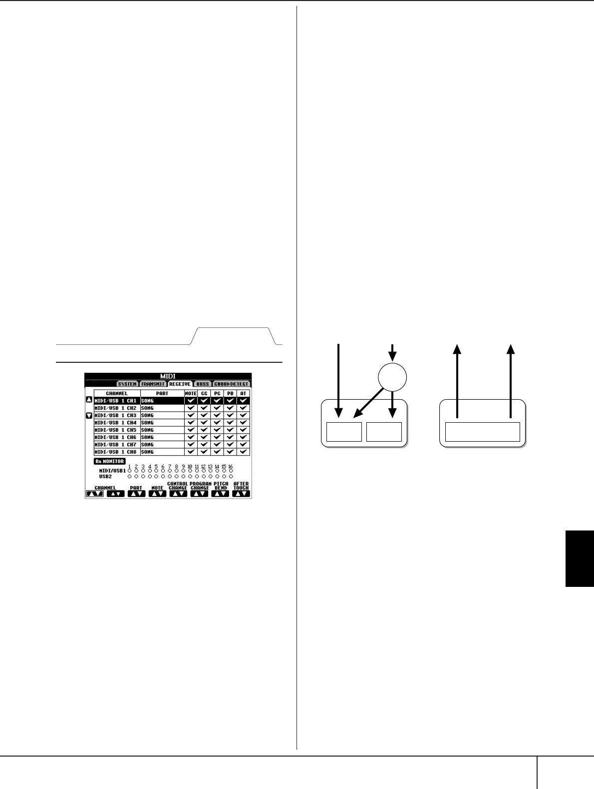
MIDI Receive Settings
The explanations here apply to the RECEIVE display to
be called up in step 4 of the “Basic Operation” on
page 177. This determines which parts will receive
MIDI data and over which MIDI channels the data will
be received.
Operation
Select the channel to be received and the part via which
the selected channel will be received. You can also
determine the types of data to be received.
● The PSR-OR700 can receive MIDI messages over
32 channels (16 channels x 2 ports) by USB con-
nection.
● With the exception of the next two parts, the
configuration of the parts is the same as those
already explained elsewhere in this manual.
• KEYBOARD
The received note messages control the instrument’s
keyboard performance.
• EXTRA PART 1-5
There are five parts specially reserved for receiving
and playing MIDI data. Normally, these parts are not
used by the instrument itself. The PSR-OR700 can be
used as a 32-channel multi-timbral tone generator by
using these five parts in addition to the general parts.
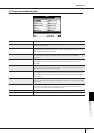
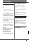
● Rx MONITOR
The dots corresponding to each channel (1–16) flash
briefly whenever any data is received on the channel(s).
n
Parameter Lock
You can “lock” specific parameters (e.g., effect, split point, etc.) to
make them selectable only via the panel controls (page 133).
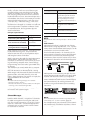
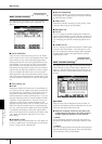
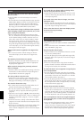
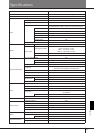
■ MIDI transmission/reception via the USB ter-
minal and MIDI terminals
The relationship between the [MIDI] terminals and the
[USB] terminal which can be used for transmitting/
receiving 32 channels (16 channels x 2 ports) of the
MIDI messages is as follows:
RECEIVE display
MIDI/USB1
01–16
USB2
01–16
USB2USB1
MIDI/USB 01–16
[MIDI IN] jack
MIDI reception MIDI transmission
[USB TO
HOST] jack
[MIDI OUT] jack
[USB TO
HOST] jack
Port
handling
Merge
Merge