


5
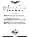
this cable to the Input of your effects unit. To send the
processed signal back to the YCS100, connect the
output of the effects unit to the Rtn jack of the YCS100.
The Send Level control enables fine adjustment of the
signal being sent to the external effects unit. The front
panel mounted EFX Return controls will allow you to
adjust the amount of effect return to each individual
channel. As an example you can set up a very lush
chorus sound in Channel 3 yet still have a dry chunky
sound set up in Channel 2 without having to do a
pedal dance. Simply switch back and forth between the
channels and the sound will already be there.
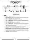
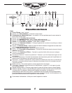
Amp In & Pre-amp Out
25
The Amp In and Pre-Amp Out jacks can be used as
a loop-thru for guitar pedals or other effect devices.
Simply plug a ¼-inch cable from the Pre-Amp Out jack
of the YCS100 to the input of the effect unit or pedal.
Plug another ¼-inch cable from the output of the effect
unit, or pedal, to the Amp In jack of the YCS100. This
is handy when you have devices that are intended for
insertion into the signal chain. The signal level at this
point is -10dBV so it will work with most guitar effect
pedals as well as professional rack equipment.
DIN Footswitch Jack*
22
The DIN footswitch jack on the rear of the YCS100 is
intended to connect with the Traynor TFS-4 footswitch
pedal via a standard MIDI/sync cable. This will allow
the user to access the three individual channels and
the Solo volume boost function via the foot-controller.
With the TFS-4 connected, the channel selection can
still be achieved via the front panel switches; the Solo
function will be overridden by the foot-controller.
¼ -inch Footswitch Jack*
23
Connecting a latching dual footswitch, such as the
Traynor TFS-2, to the ¼-inch TRS Footswitch jack will
allow separate defeating of the Reverb and Effects
return signals. This will defeat the return signals in all
three channels at once. LED’s will indicate the status
mounted on the TFS-2.
*The switching is accomplished with internal relays so
there are no audio signals flowing through the footswitch
cables. Footswitch-induced noise is never an issue. The
YCS100 ¼-inch footswitch is compatible with most after-
market latching dual footswitch pedals.
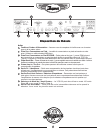
Speaker Jacks and Impedance Selector Switch
27
The dual ¼-inch jacks allow convenient
connection of external speaker cabinets.
Insure that speakers are properly
connected and that the impedance
selector is set to the appropriate position
before operating the amplifier.
Phones/Line Out, XLR Balanced Line Out Jacks
and Level Control
27
For maximum versatility, The YCS100 has both ¼-inch
and XLR Line Outs. The ¼-inch output also doubles as a
headphone jack. This Phones/Line Out jack can be used
with any stereo headphone. The signals sent from these
outputs are post-master and have speaker simulator
compensation. These outputs will remain active when the
amplifier is in standby mode so the YCS100 can be used
as a pre-amp for recording or simply for silent practicing.
When operating in standby mode, speakers do not need
to be connected. If you are using the XLR line out as an
output to a mixing console for live sound reinforcement
the Tuner Mute will also mute these outputs.
Amplifier Mode
28
The YCS100 output stage can be operated in either
100-watt or 30-watt modes. While in 100-watt (Class
AB) mode. The amp will produce a full 100-watts of
output power; this is for situations where maximum
headroom is required. For situations where more tube
warmth is required at lower volume levels, the YCS100
can be switched to operate in 30-watt (Class A mode).
This is done by cutting the operating voltage to the
output tubes in half and automatically adjusting the bias
level to operate in Class A mode. All four output tubes
still operate in the 30-watt mode but at a reduced power
level, therefore increasing output tube longevity.
The output impedance of the YCS100 power
amplifier changes in different power modes
therefore the MINIMUM speaker load impedance
also changes. In 30-Watt mode, you can choose
between a MINIMUM load impedance of 2-ohms or
4-ohms. When in 100-Watt mode, the MINIMUM load
impedance choices are 4-ohms or 8-ohms.
Tech Note: Knowing the MINIMUM load impedance of an
amplifier is important when connecting speaker cabinets to
the amplifier. Each speaker cabinet has a rated NOMINAL
impedance that directly affects the sound and performance
of the power amplifier. If you use speakers that load the
amplifier too much (i.e. using a 2-ohm load on an amplifier
rated at 8-ohms), you will make the amplifier exceed it’s
capability and will lead to shorter tube life.
Speaker Cabinets
You can either connect speakers in parallel or series.
Most speaker enclosures have parallel output jacks that
enable users to chain speaker extension cabinets
together. Series connections are rarely used.
The easiest way to describe this is if
you have two 8-ohms speaker cabinets
connected in parallel the resulting
impedance would be 4-ohms (16-ohms if
they were wired in series).
•
Q
U
A
L
I
T
Y
&
I
N
N
O
V
A
T
I
O
N
•
•
E
S
T
A
B
L
I
S
H
E
D
1
9
6
3
•