


6
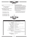
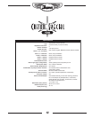
Specifications
Type
YCS100 Tube Guitar Amplifier
Minimum Impedance (ohms)
2 (30-watt mode), 4 (100-watt mode)
Input Channels
3
Channel input
1/4 inch phone
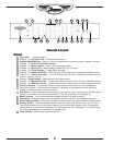
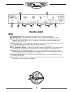
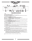
Channel 1, 2, 3 - Controls
Gain, Volume,Treble, Mid, Bass, Reverb, and Effects
Channel 1, 2 - Switches
Boost, Scoop and Modern
Channel 3 - Switches
Boost, Bright and Modern
Channel 2 - Inputs
Shares Ch 1 input
Channel 3 - Inputs
Shares Ch 1 input
Channel Switching
Yes, footswitchable
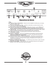
Line Out (type / configuration)
Speaker Compensated XLR Balanced, 1/4" unbalaced
Effects Volume
Yes, 3 individual returns
Effects Loop / Location
Yes / Rear
Effects Footswitch / Function
Yes / Internal reverb and external effects globally defeatable
Internal Reverb / Effects
Accutronics® Spring Reverb
External Speaker Output / location
Yes / rear (Dual selectable Impedences)
Headphone Jack
Yes
Other Features
Standby Switch, Auto tube matching, DC filaments on preamp
tubes, Tuner mute, Separate tuner output, Footswitchable
Solo boost, Presence & Resonance
Dimensions (DWH, inches)
11.5 x 26.5 x 10.5
Dimensions (DWH, cm)
29.25 x 67.5 x 26.75
Weight (lbs / kg)
44 / 20
The formula to calculate Total Impedance for a parallel
system is …
1/R
T
= 1/R
1
+ 1/R
2
+ 1/R
3
+1/R
4
…
R = Rated Speaker Impedance
R
T
= Total Speaker Impedance
R
1
… = Speaker Impedance
Examples (Speaker cabinets connected in parallel)
One 4-ohm cabinet = 4-ohms
Two 4-ohm cabinets = 2-ohms
Four 4-ohm cabinets = Not Recommended
One 8-ohm cabinet = 8-ohms
Two 8-ohm cabinets = 4-ohms
Four 8-ohm cabinets = 2-ohms
One 16-ohm cabinet = 16-ohms
Two 16-ohm cabinets = 8-ohms
Four 16-ohm cabinets = 4-ohms
Eight 16-ohm cabinets = 2-ohms
Replacement Tube Selection & Bias**
The YCS100 comes from the factory equipped with
matched EL34EH output tubes. The circuitry has been
designed to accommodate any type of EL34/6CA7 as
well as any type of 6L6/5881 output tubes, as long
as the four output tubes be of a matching type. The
amplifier has also been equipped with bias sensing
points for each of the output tubes as well as a bias
adjustment pot that can all be accessed without
removing the chassis from the box. This makes tube
replacement quick and easy.
**We recommend adjusting the zero signal bias to +250
mV +/-30mV DC at each of the test points. Bias adjustment
should be done with the amplifier configuration in the 100
Watt mode. Please refer servicing to qualified personnel.