


8
Digital Effects Processor
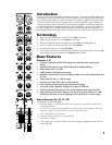
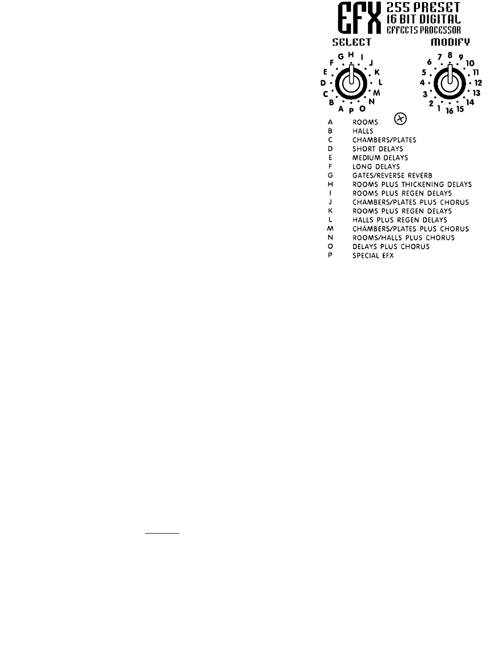
The internal Digital Effects Processor is a
full 16 bit, 20kHz bandwidth DSP-based
effects subsystem developed by Applied
Research & Technology in Rochester,
New York. It has been custom pro-
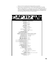
grammed with 255 effects ranging from
reverb to echo and special effects.
The selection of effects was determined in
collaboration with a panel of sound engi-
neers experienced in live performance mix-
ing. The panel was asked to choose effects,
which would be of the most practical use
in actual, live performance situations. As a
result you will find the internal system to be
more than adequate for most application
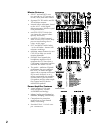
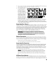
EFX Footswitch/Send Jack
A standard on/off footswitch (optional)
plugged into this jack will enable you to
turn the internal effects system on and off.
Optionally, this jack may be employed to
feed the EFX signal to an external effects
unit the output of which could be returned
via an input channel - perhaps channel
9/10 or 11/12 if the effects unit is stereo. In
this mode, the channel fader would become the master effects return control, there-
fore be sure to set that fader fairly low and adjust to desired levels. Be sure to turn the
EFX send control off in order to avoid creating a loop. Also, be sure to pull the EFX
MASTER fader down to the off position.
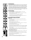
Phones Jack, Level Control & Sources
The PHONES jack accepts standard stereo headphones and is located in the upper
right area of the panel. The PHONES level control is located in the lower right area.
The source for all headphone signals is the MONitor bus until a CUE button is
depressed at which time only the cued channel can be heard through the phones.
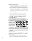
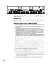
Level Meters
These meters follow either the Left and Right MAIN bus activities or a mono mix of
the mains on the Left-meter and monitors on the Right-meter, all depending on the
position of the EQ/AMP ASSIGN button. If either or both CLIP lights at the top of the
level meters is flashing too much of the time, lower the appropriate MAIN MASTER
level to avoid possible distortion on peaks.
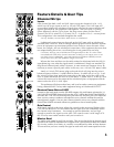
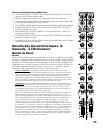
Amp 1 & 2 Inputs
These are switching jacks, which enable you to directly access either or both chan-
nels of the built-in power amplifier while disconnecting them from normal internal
functions. This permits you to insert an external-EQ, a processor/crossover (e.g. élite)
or a compressor/limiter between the mixer section’s POST EQ LINE OUTPUTS and
the AMP 1 & AMP 2 INPUTS thus providing the 100% signal processing essential for
these functions to work properly.
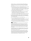
User tip: If you have an electronic-crossover or processor/crossover, you can drive
subwoofers and full-range cabinets in a biamped system with the AP312. The hookup
goes as follows:
1. With the EQ/AMP ASSIGN button down in the MAIN/MON position, run a patch
cable from the POST EQ MAIN (L) LINE OUTPUT to the input on an electronic
crossover/processor.
2. Now run a second patch cable from the low-frequency or subwoofer output on
the crossover to the AP312’s AMP 1 INPUT and a third patch cable from the
crossover’s high-frequency or full-range output to the AP312’s AMP 2 INPUT.