


3
Feature Details & User Tips
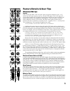
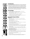
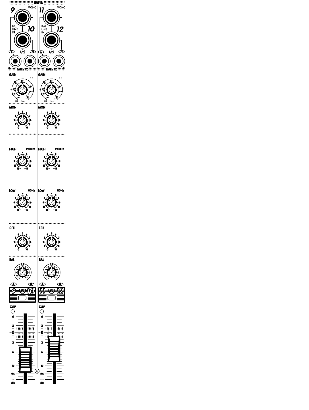
Channnel Strips
Inputs
Each channel has both a MIC and LINE input (except for channels 9/10 & 11/12
which have RCA type inputs as well as 1/4-inch TRS inputs). The LINE input will
accept either balanced or unbalanced signals from all types of sources and the MIC
input is optimized for low-impedance microphones. The LINE input is Tip-Ring-
Sleeve balanced, with the Tip in phase, the Ring reverse phase and the sleeve,
Ground. The XLR is wired Pin 1= Ground, Pin 2 = in phase & Pin 3 = reverse phase.
This configuration is the standard throughout the world.
User tip: Problem; Hum and Buzz When Source is Unbalanced...
Unbalanced connections may be made to the LINE input with an unbalanced
shielded cable. However, field or leakage-induced ground currents between separate
pieces of equipment can sometimes produce hum and buzz. Most electronic instru-
ments, for example, still use unbalanced connections. If the equipment has more than
one output feeding the mixer, even floating the circuit ground may not help.
CAUTION: We urge you to NEVER remove the ground-pin on the AC cord or other-
wise disable the earth safety Ground connection as doing so can expose you to a seri-
ous shock hazard. Additionally, your radio interference problems will likely increase
and in some cases your hum problems will get even worse.
What to do: Hum and buzz can be safely reduced or eliminated with the AP312’s
input balancing, even when the signal source is unbalanced, Simply use standard Tip-
Ring-Sleeve balanced patch cables. However, in some worst-case instances it may be
necessary to create a special patch cable. In this case, use a 1/4-inch TRS (stereo) cable.
Attach a 1/4-inch TRS (stereo) plug to the end which will plug into the mixer’s
balanced-input as follows; 1) solder shield to Sleeve, 2) solder wire #1 to Tip, 3) sol-
der wire #2 to Ring. Now attach the mono plug to the other end of the cable as fol-
lows: 4) solder the shield and wire #2 to the Sleeve, 5) solder wire #1 to the tip. Now
connect this mono end to the output of the unbalanced piece of equipment and the
stereo end to the AP312’s LINE input.
This technique will always reduce hum, and it can be used to connect any equipment
having a Balanced INPUT to any other equipment having an Unbalanced OUTPUT.
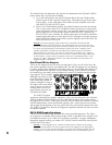
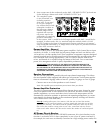
Phantom Power Button & LED
Located on the back panel near the SPEAKER outputs, this push-button activates the 24
Volt PHANTOM POWER feature built into the AP312. When the PHANTOM POWER is
activated, the +24V LED on the front panel (just below the PHONES jack) will illuminate.
Now you may connect condenser microphones to any channels without the need for
external power supplies. You may also connect dynamic mics to any channels with the
PHANTOM POWER activated without any problems or loss of sound quality.
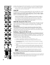
Gain Control
With signal applied to the input, adjust this control so that occasional flashes of the
CLIP LED are observed. This will ensure that the signal level fits comfortably within
the channel strip’s headroom ~ low enough to prevent distortion, and yet high
enough to preserve the signal to noise ratio. This control covers a wide range of 78
dB, so it may seem rather sensitive until you’re used to it.
Monitor Send
The MON send control is pre-EQ & pre-fader. This means that the bit of channel signal
it sends to the MASTER MONitor bus is tapped off at a point ahead of both the channel
EQ circuitry, and the level fader. As a result it is not affected by either of these features.
This means that you have a totally flat signal to work with and custom-equalize for the