


2
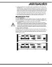
Channels 5 and 6 have very high impedance, unbalanced ¼-inch inputs which are opti-
mized for instruments such as electric basses, acoustic electric guitars etc. Stereo channels
7/8 and 9/10 have left and right ¼-inch balanced LINE in jacks as well as mono gold-plated
XLR low impedance microphone inputs. The ¼-inch inputs may be used to connect a stereo
CD player, tape deck or an additional mixer etc. A phono pre-amplifier must be connected to
the M810/M1610 inputs for optimum turntable performance.
Connecting signals to both types of inputs on any one channel (MIC and LINE in) is not
recommended. To do so may change the gain of the input circuit.
Note: You may connect a stereo source to channels 1 through 6 but you must use two chan-
nels, one for left and one for right and Pan appropriately or sum to mono using a ‘Y’ cable.
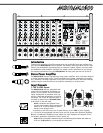
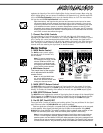
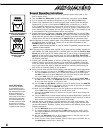
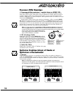
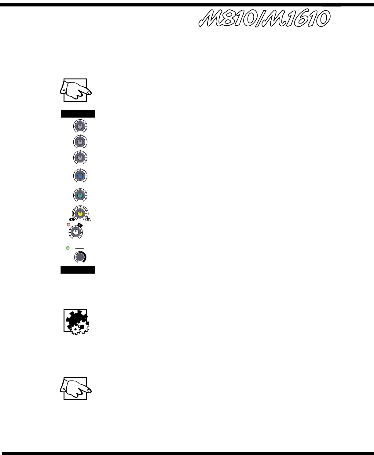
2. Channel 1-6 TRIM Controls & SET LEDs
The first 6 mono channels of the M810/M1610 have been equipped with an input TRIM
control and are also protected by an overload protection circuit. The TRIM controls are used
to make sure that an ideal signal level is flowing through the channel, no matter what the
input source. Each channel has a green LED that will flash when the proper signal level has
been reached. The channel overload protection circuit will provide additional protection from
clipping on peaks of up to 16 dB above normal operating levels.
To set the TRIM
i. Turn down the channel LEVEL control,
ii. With a normal signal present at the input, turn up the TRIM control until the green LED
just starts to flash (when the signal peaks).
iii. You can then use the LEVEL control to set the channel volume level. Increasing the
TRIM beyond this point will compress the signal on that channel.
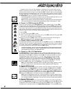
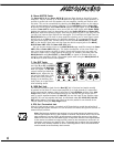
3. Channel LEVEL Controls & CLIP LEDs
This adjustment determines the signal level sent to the MAIN mixing bus. The CLIP LED will
illuminate when the channel’s overall signal level is 3 dB below the onset of actual clipping.
As a result, small amounts of clip LED activity are acceptable, however frequent or continu-
ous activity indicates the need to turn down the LEVEL control.
In audio terminology, a bus is a mix-down channel where all the signals from the input
channels are blended into one signal. The M810/M1610 has 5 busses: MAIN (left and
right), MONITOR, EFFECTS and RECORD OUT.
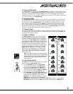
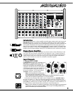
4. Channel Lo, Mid, & Hi Equalization
The M810/M1610 tone controls adjust the bass, middle and treble frequencies for each
channel independently. Center frequencies have been carefully selected to help achieve the
best quality of sound. Bass is centered on 80 Hz, Mid at 2.5 kHz and the Hi is at 12 kHz.
The adjustment range for each control is +/- 15 dB. These parameters provide versatile
equalization consistent with the clean simplicity of the M810/M1610’s design. As with
equalizers, boosting one or more frequencies increase the channel’s level. If the channel
is already at a high level, clipping may occur, in which case the clip LED will illuminate.
Reduce the LEVEL setting and/or the Equalizer if clip activity is excessive.
Note: The center position reflects a neutral or flat EQ control setting; however, turning
down EQ settings can be used effectively to reduce feedback and/or distortion).
5. Channel MON Controls
The MON control (monitor send) on each channel varies the amount of signal being sent to
the monitor bus in the M810/M1610. In the mono channels the MON signal is pre-LEVEL
control, post-EQ and post-TRIM. It is taken before the LEVEL control so the monitor signal
can be mixed independently of the MAIN mix. As a result, channel EQ and TRIM settings do
affect the sound of the monitor signals, while the channel LEVEL controls do not affect the
MON signal. The MON signal in the stereo channels is pre-LEVEL and pre-EQ.
Note: With an independent monitor mix, it may be beneficial to connect a graphic equal-
izer between the MON output and the monitor amplifier (Power AMP IN B, external ampli-
fier or powered speakers, depending on how you have it set up) to help control feedback.
6. Channel EFX Controls
The EFX control (effects send) for each channel adjusts the level of the channel signal being
sent to the M810/M1610 effects bus. This signal is post-LEVEL control and post-EQ, the sound
is affected by both the channel EQ controls and the channel LEVEL control. The signal from
the effects bus is internally routed to the Digital Effects Processor. The channel EFX control
-3
-20
+6
+3
0
-10
+10
0
0
-
1
Set
LEVEL
Trim
dB
Line Mic
0
10
-15 +15
dB
-15 +15
dB
-15 +15
dB
0
5
2 8
7
6
4
3
91
10
clip
Pan
Mon
EFX
Lo
Mid
Hi
1