


5
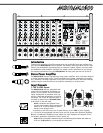
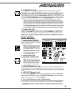
10. Power LED & Switch
The Power LED lets you know that the M810/M1610 is plugged in, turned on and all sys-
tems are normal. The Clip/Protect LEDs normally indicate clipping in the amplifiers. They
will remain illuminated and the power LED will turn off in the unlikely event that the
amplifiers overheat or if DC voltage is detected on the output. The AC power on/off switch
is on the rear panel of the M810/M1610.
11. Phantom Power
The Phantom Power LED indicates that 48 volts of DC phantom power is present on the
XLR microphone inputs for powering condenser microphones. Regular dynamic mics may
also be used while the Phantom Power is on. Connecting a microphone of either type
with phantom power on and the channel LEVEL up will create a large transient, result-
ing in a loud, potentially damaging pop. When setting up, either turn off the AC power,
the phantom power, or set all channel levels to zero. The Phantom Power push-button is
located on the rear panel between the speaker output jacks.
12. Tape/CD Input
Left and right RCA inputs are provided to connect a CD player, cassette player or other ste-
reo source to the mixer. These inputs are routed directly to the main bus, the Tape/CD con-
trol adjusts the amount of signal.
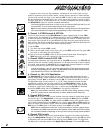
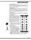
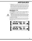
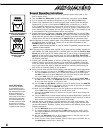
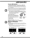
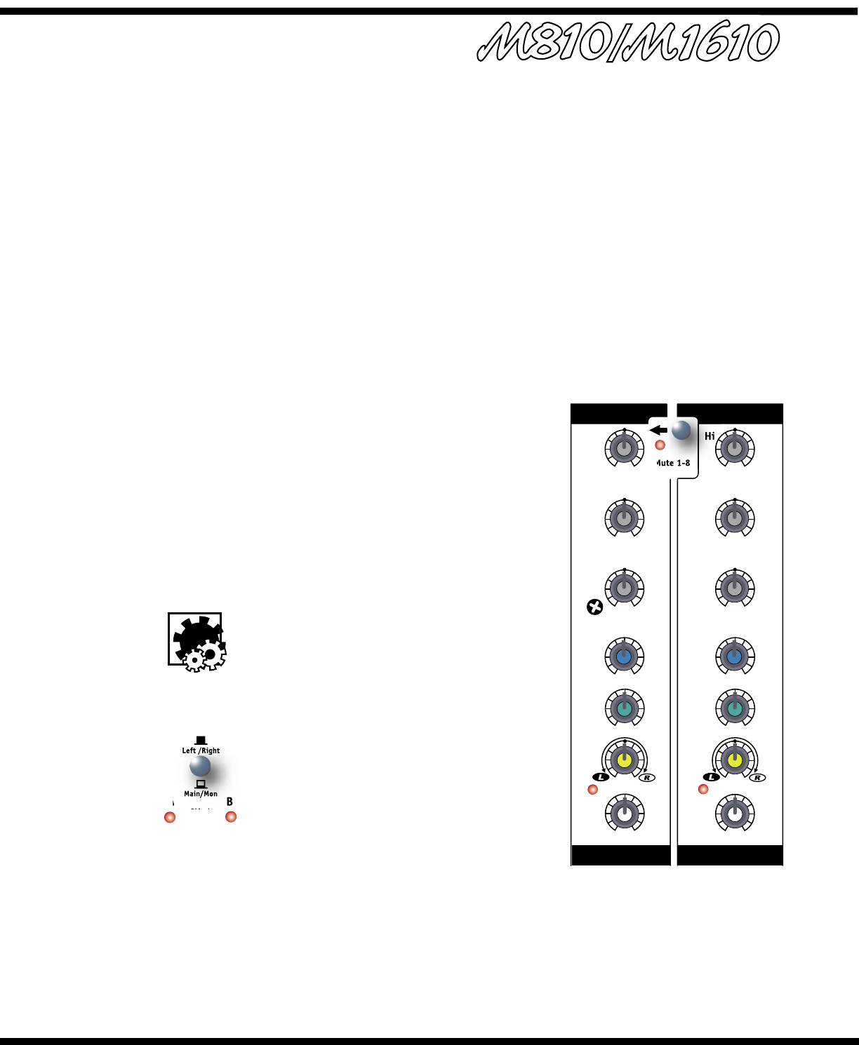
13. Mute 1-8 Switch
The M810/M1610 includes a feature that enables
users to instantly mute channels 1-8. Depressing
the Mute 1-8 switch will mute channels 1-8 signals
being sent to the Left, Right, Mon and EFX busses
(the signals from these channels will still be sent to
the record bus and will not be muted. Channel 9/10
will remain active, leaving this channel open for
allowing a microphone or CD player, cassette player
or other stereo source to be heard over the Left,
Right, Mon and EFX busses. This feature lets you
mute the mics and instruments on stage and still
allows you to make announcements or play music
during breaks. When the band returns to perform,
simply deactivate.
Note: The Tape/CD input in the master section
also remains active. While muted, the Mute LED
flashes at a slow rate (long on/short off) and the
clip LEDs of all the muted channels alternate
long off/short on.
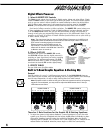
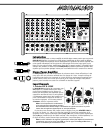
14. Amp Assign Switch
The MAIN controls determine the level of the signal
routed through the Amp Assign switch:
i. In the Left/Right position, the Amp Assign
switch directs the left and right MAIN master
signals through Equalizer A and Equalizer B.
The signal goes to the left and right inputs of
the built-in power amplifier (Amp A and Amp B)
and to the left and right post-EQ OUT jacks.
ii. In the Main/Mon position, the Amp Assign switch
sums the left and right MAIN signals into a single,
mono signal while directing it to the input of
Equalizer A, the output of which goes to both the
Amp A power amp channel and to the Post-EQ
MAIN OUT jack. Additionally, the signal from the MON master’s output is routed through
Equalizer B and then to both the Amp B power amp channel and to the MON Out jack.
Mute 1-8
0
10
0
10
0
5
2 8
7
6
4
3
91
10
0
5
2 8
7
6
4
3
91
10
0
5
2 8
7
6
4
3
91
10 0
5
2 8
7
6
4
3
91
10
-15 +15
dB
-15 +15
dB
-15 +15
dB
-15 +15
dB
-15 +15
dB
-15 +15
dB
clip clip
9/10
7/8
7/8
9/10
Bal
Mon
EFX
Lo
Mid
Hi
Bal
Mon
EFX
Lo
Mid
Hi
LEVEL
LEVEL
S T E R E O S T E R E O
Main/Mon
Left /Right
A B
Amp
Assign
Clip/
Protect