26 en | Connection VEZ-400 Mini PTZ Dome
F.01U.252.635 | 2.0 | 2011.09 User Manual Bosch Security Systems, Inc.
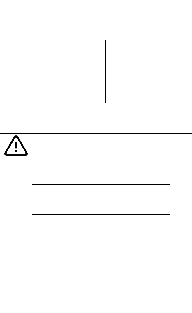
Connecting the Alarms
Use the following table to connect alarm wires to the 8-pin
terminal block from the camera:
Table 6.4 8-pin Terminal Block Connections
6.4 Power Connections
The recommended power cable is a 2-conductor, 14-18 gauge
cable, depending on the distance.
6.5 Camera Settings
The camera can communicate with external switching devices
such as a multiplexer or a DVR by setting the Rotary and Dip
switches. Refer to the tables below for setting the camera’s ID
and selecting the protocol. The camera's Dip switches can be
accessed by removing the dome cover, and are located on a
PCB attached to the camera base.
Number Signal Color
1 NC Yellow
2 COM Orange
3NOGreen
4AL3Blue
5 GND ALM Black
6AL2Violet
7AL1Gray
8AL0Brown
CAUTION!
The camera unit accepts 24 VAC power only. Do not connect
120 V or 230 V to this camera!
A/W 14 AWG
(2.5 mm)
16AWG
(1.5 mm)
18 AWG
(1.0 mm)
2 A / 43 W (with heater) 250 m
(820 ft)
150 m
(492 ft)
100 m
(328 ft)


