Turbomachinery Package Specification Titan 250 Generator Set
• Graphics in a separate window for simultaneous viewing of text with associated
illustration
• PDF version for printing
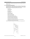
17.5.5 Service Parts List
Identifies operational service parts and tooling. Once engineering has been finalized and
manufacturing bills are available, Solar's Service Parts department creates a detailed
listing of service parts from the actual equipment manufacturing bills of material.
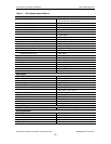
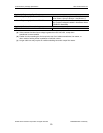
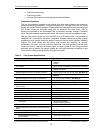
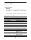
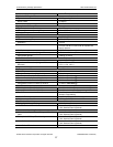
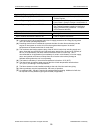
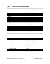
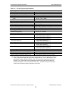
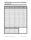
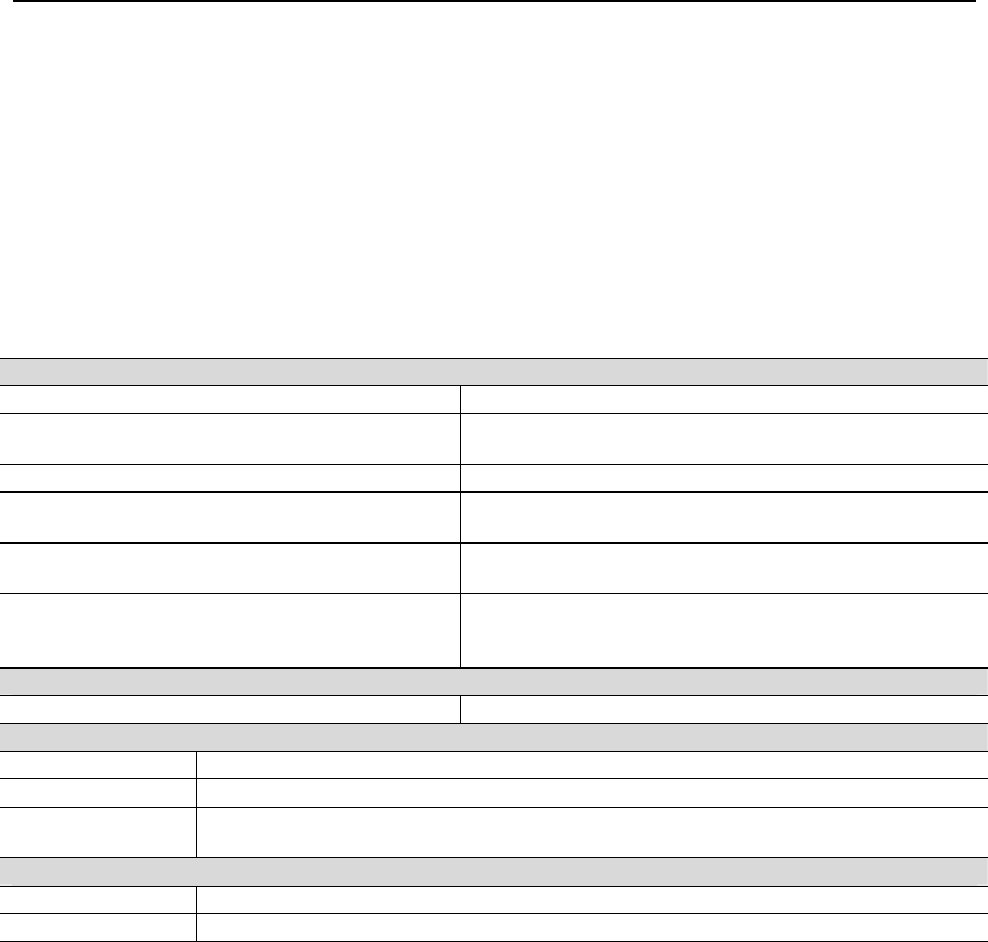
Table 14. Preservation, Installation, and Documentation Specifications
Mechanical Installation Requirements
Mounting
Space Between Units In Multiple-Unit
Installations
A Minimum of 2.5 m (8 ft)
Lube Oil Cooler(s)
Top of The Lube Oil Cooler(s)
Not Be More Than 9 m (30 ft) Above The Bottom of
The Package Frame, See Note (a)
Total oil volume of “Outgoing and Return”
Lines
1282 L (340 gal)
Total Combined Pressure Drop of The
Supply and Return Lines and Lube Oil
Cooler(s)
Should Not Exceed 345 kPag (50 psig)
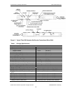
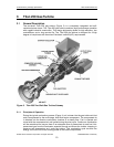
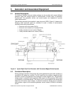
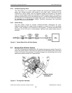
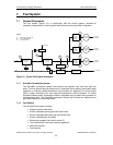
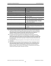
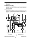
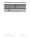
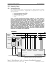
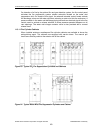
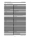
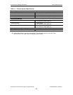
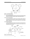
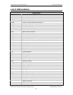
Start, Fuel, Lube, Air/Drain System Schematics
Compliance American National Standards Institute (ANSI) Y32.10
Solar’s Applicable Engineering Specifications
ES 9-4 Interpretation of Drawing Requirements
ES 9-76 Traceability Requirements Critical Parts, Engine and Related Systems
ES 2231
Standards and Practices for The Design and Installation of Cable Channels and TC
Rated Cables Installed In Class 1, Division 2 Hazardous Areas
Solar’s Applicable Product Information Letters
PIL 184 Documentation for New Equipment
PIL 097 Package Preservation and Preparation for Shipment
Notes:
(a) This is to prevent oil tank flooding in the event of a drain back.
© 2008 Solar Turbines Incorporated. All rights reserved. TPS250GS/908 - Preliminary
69