Commander GP User Guide
Issue code: gpxu2
D-12 Menu 0 Parameters
0.18 Brake release indicator
RO Bit P
0 ~ 1
Applicable to Macros...
01234567
0.18 indicates as follows:
0.18 Brake...
0 Applied
1 Released
0.19 S-ramp da/dt limit
RW Uni
0 ~ 3000.0 3.1 s
2
/100Hz
Applicable to Macros...
01234567
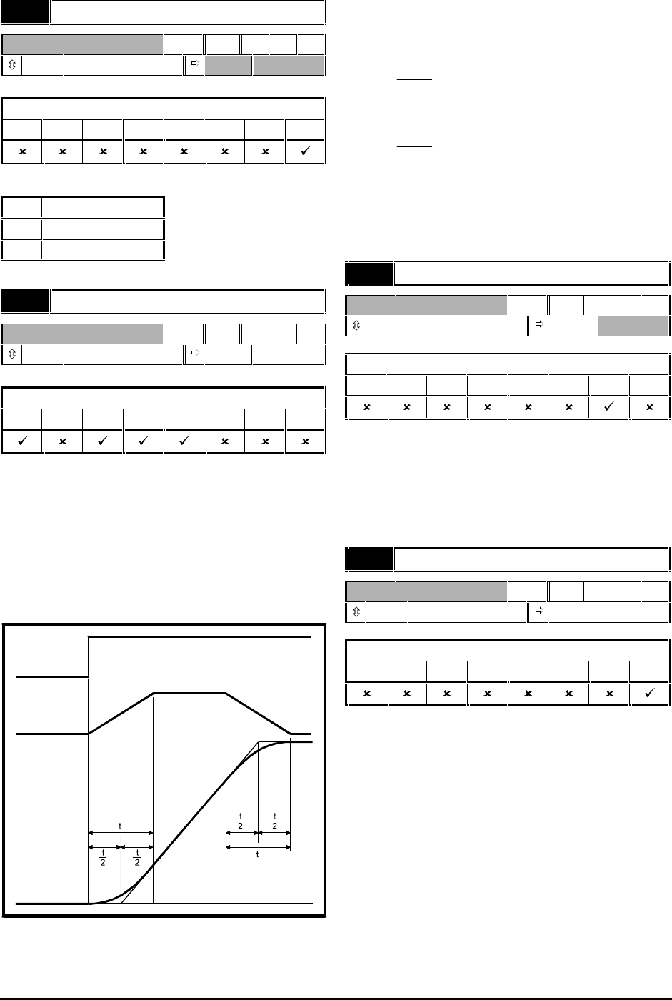
Use S-ramp to limit the rate of change of
acceleration and deceleration at the start and end
of ramps.
If a different rate of change of acceleration and
deceleration is required, set 0.19 S-ramp da/dt limit
at the required rate. (The acceleration and
deceleration rates are set in parameters 0.03 and
0.04.)
Speed demand
Acceleration
Actual speed
Time
Figure D–3 S-ramp time durations
Refer to Figure D–3. The time duration t of the
curved sections can be calculated as follows:
For acceleration:
t ==
[. ]
[. ]
019
003
For deceleration:
t ==
[. ]
[. ]
019
004
In comparison with a normal ramp, S-ramp increases
the total ramp time by the value of t, since an
additional
t
/
2
is added at the beginning and end of
the ramp.
0.19 Hold zero speed enable
RW Bit
0 ~ 1 0
Applicable to Macros...
0123
567
Set at 0 to cause the IGBT bridge to become disabled
when no RUN signal is applied. The motor shaft will
then be free to rotate.
Set at 1 to keep the
IGBT bridge enabled when no
RUN signal is applied. The Drive will apply torque to
hold the motor shaft stationary.
0.19 Current threshold
RW Uni P
0.0 ~ 100.0 0% I
max
Applicable to Macros...
0123
567
Set 0.19 at the required percentage of I
max
(see
below). This value must ensure that adequate
current will flow through the motor to control the
load when the brake is released.
I
MAX
= FLC x 150%
