7. Circuit Diagrams
7.1 General
The air heater Air Top 2000 S may be operated
using the control dial (rated value transmitter/switch)
or with the control dial and a combination or
standard timer. The circuit diagrams (Figs. 702 to 704)
show the possible circuits 12 or 24 Volt with
control element
combination timer
control element and standard timer
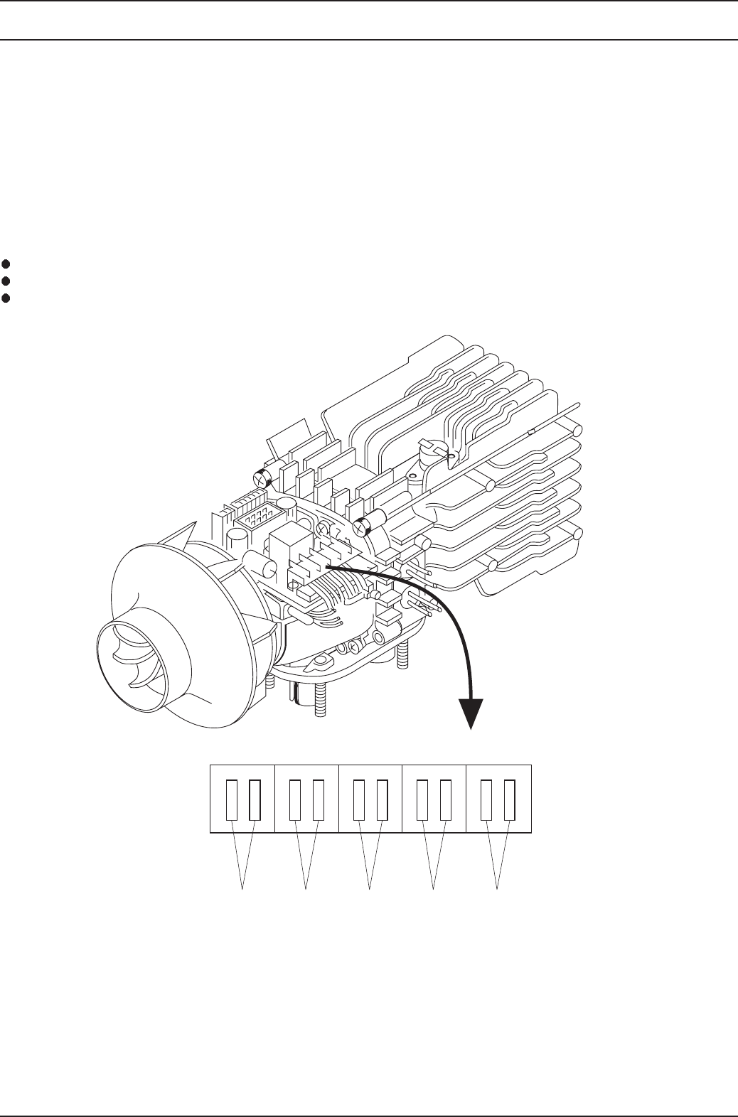
Fig. 701 shows the terminal pin assignment.
X1 = Connection, Combustion and Heating Air Fan
X2 = Connection, Dosing Pump
X3 = Connection, Flame Sensor
X4 = Connection, Glow Plug
X5 = Connection, Temperature Limiter
701
wolleyteloiv brown eulbkcalb
4X1X X3 5X2X
Fig. 701 Terminal Pin Assignment, Air Top 2000 S
Air Top 2000 S
7 Circuit Diagrams


