704
7 Circuit Diagrams
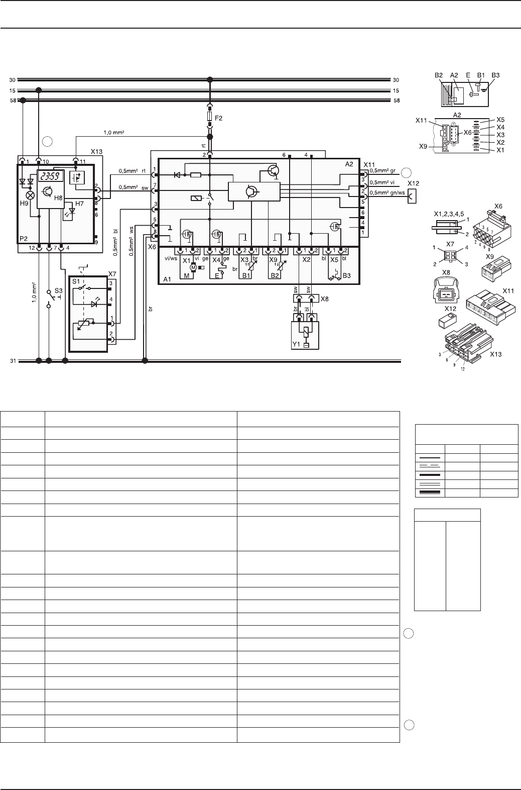
Air Top 2000 S
Wire Gauges
< 7.5 m 7.5 - 15 m
0.75 mm
2
1.0 mm
2
1.5 mm
2
2.5 mm
2
4.0 mm
2
1.5 mm
2
1.5 mm
2
2.5 mm
2
4.0 mm
2
6.0 mm
2
bl
br
ge
gn
gr
or
rt
sw
vi
ws
Wire Colours
blue
brown
yellow
green
grey
orange
red
black
violet
white
Fig. 704 Circuit Diagram Automatic Control Air Top 2000 S,
12V/24V with Control Dial and Standard Timer
krameRerutalcnemoNmetI
0 S002 poT riAretaeH riA1A
A2 Control Unit
B1 Flame Sensor
B2 Temperature Sensor
B3 Temperature Limiter
E Glow Plug
4821 J EAS esuF talFA51 V21/A01 V42 esuF2F
,noitanimulli hctiws taeh tnatsnI)P meti ni( der DEL7H
standy indication,
operating indicator light
H8 Heating symbol in display (in item P) Operating indicator light,
overheat indication
noitanimulli lobmyS)P meti ni( thgiL9H
M Motor
P2 Standard timer
hctiwS gnitteS eulaV detaRtnemelE lortnoC1S
lortnoc etomer gnitaeh tnatsnIhctiwS3S
2A meti foelop-2 noitcennoC5X-1X
2A meti foelop-8 noitcennoC6X
1S meti foelop-4 noitcennoC7X
X8 Connection 2-pole
2A meti foelop-6 noitcennoC11X
)eriw-K( sisongaiDelop-1 noitcennoC21X
P meti foelop-21 noitcennoC31X
Y1 Dosing Pump
with plus from terminal (15/75)
to connection 10:
permanent operation during
instant heating as long as
ignition on
without plus to connection 10:
heating time programmable as
required (10 min to 120 min),
default setting 120 min.
Connection X11/2 and X11/3
for TRS function only
2
1
? ?
?
1
2


