


1
150-Watt Module
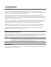
About This Manual
This manual provides information for the Agilent 60501B 150-Watt Electronic Load Module. It is designed as a
supplement to the Agilent 6050A/6051A Multiple Input Mainframe Electronic Load Operating Manual (part number 06050-
90001). Four tables provide the following module-specific information:
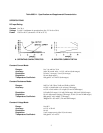
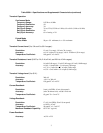
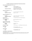
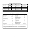
Table 60501-1 lists both the specifications and supplemental characteristics of the module. Specifications indicate
warranted performance in the 25
°
C ± 5
°
C region of the total temperature range (0 to 55
°
C). Supplemental characteristics
indicate non-warranted, typical performance and are intended to provide additional information by describing performance
that has been determined by design or type testing.
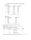
Table 60501-2 lists the ranges that can be programmed in constant current, constant resistance, and constant voltage modes.
It shows the maximum and minimum programming values for each range. Refer to this table when programming the
module locally as described in Chapter 4, or remotely as described in Chapter 5 of the operating manual.
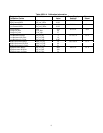
Table 60501-3 gives the factory default values of the module. Unless you have saved your own wake-up settings, the
module will be set to the factory default values whenever power is applied. See Chapter 4 in the operating manual.
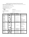
Table 60501-4 provides calibration information for the module. This information is needed to perform the annual
calibration procedure described in Chapter 6 of the operating manual.
Module Installation and Operation
Except for the module-specific information in this manual, all installation, operation, and calibration instructions are given
in the Mainframe Operating Manual. The Agilent Electronic Load Family Programming Reference Manual (part number
06060-90005) contains complete programming details that apply to all Electronic Load models.
Note: The following information in Chapter 2 of the Mainframe Operating Manual does not apply to electronic
load modules with the serial numbers listed on the title page of this manual: The section titled "Extended
Power Operation", and the section titled "Extended Power Limit". Also for these modules, change the 3-
second delay referred to under "Nominal Power Limit" to 50 milliseconds.
Items Supplied
In addition to this manual, a 10-pin connector plug is also shipped with your Electronic Load module. Refer to Chapter 3 in
the operating manual for more information.