


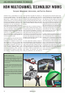
FREQUENCY MANAGEMENT, INTERFERENCE, AND PRACTICAL REMEDIES
HOW MULTICHANNEL TECHNOLOGY WORKS
32 www.akg.com
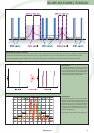
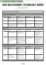
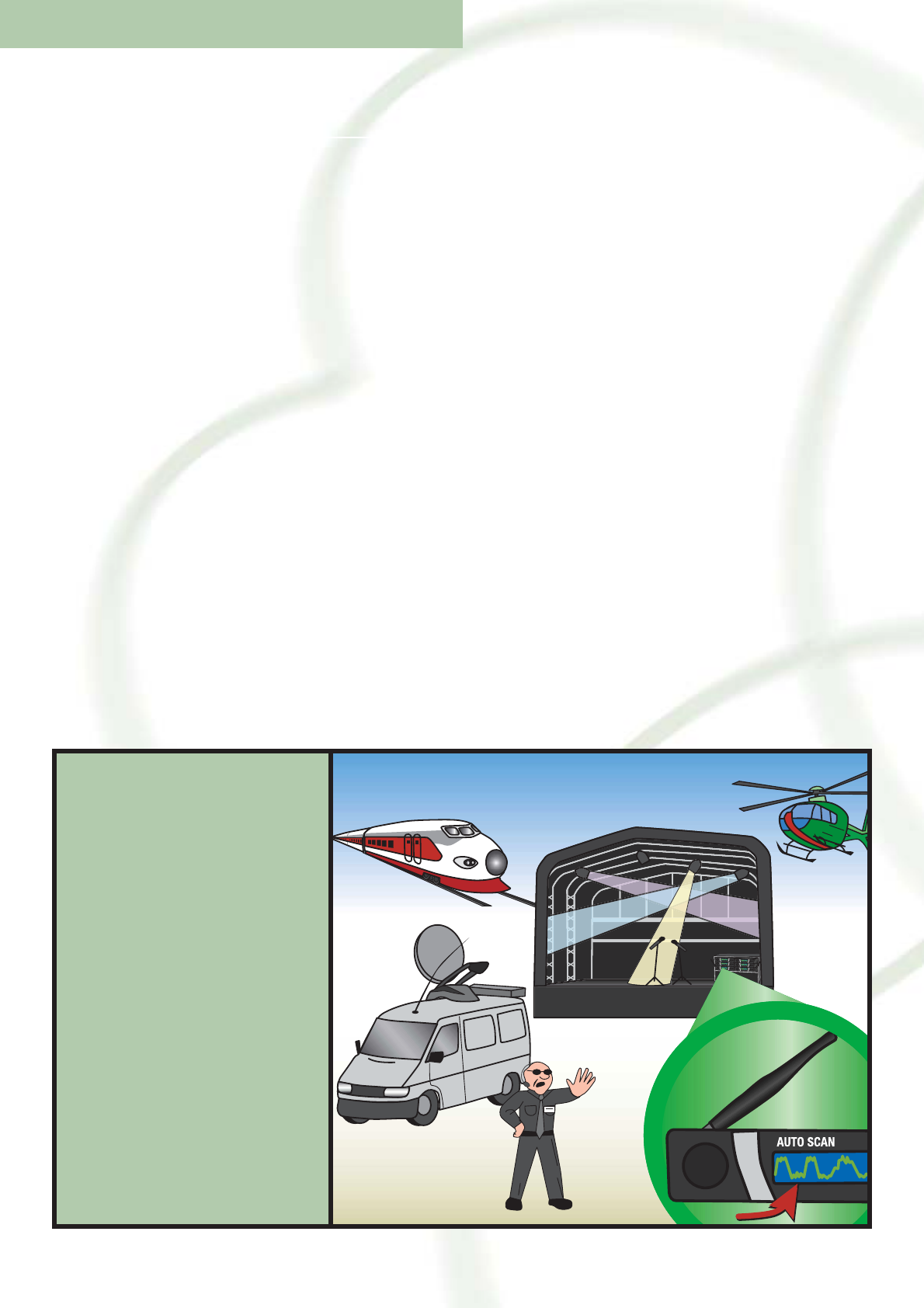
Automatic frequency setup
During concerts and other performances, a number of applian-
ces emit electromagnetic waves that may disrupt your transmis-
sion channels (outside interference). Thanks to the
“Environment Scan” function, AKG wireless systems are able to
localize such “jammers”, switching to suitable interference-free
frequencies instead.
In other words, the system automatically searches for gaps in
the fre-quency spectrum – that is, frequencies where no interfe-
rence is de-tected – occupying them with its own carrier fre-
quencies.
Important: Run Environment Scan during the soundcheck and
note the results. Do another test shortly before the performance,
as there will almost certainly be new sources of interference,
such as television and radio transmitters, or mobile phones in
the audience. This gives you time to correct any problems that
may have arisen.
Interference due to intermodulation can occur
as soon as a radio-frequency circuit consisting
of semiconductors or ferrites – like that of a
WMS receiver – handles several RF signals at
different frequencies. The number of disturbing
frequencies (intermodulation products) increa-
ses exponentially wherever several radio links
(frequencies) are used simultaneously. This
laws of physics have the biggest impact when
several radio microphones are used at the same
time. The innumerable new frequencies genera-
ted by the combination, addition and subtrac-
tion of the desired frequencies cause additional
interference. Expert management of the fre-
quencies of all radio sources designed to be
used simultaneously is therefore absolutely
essential for the problem-free operation of a
multichannel wireless system.
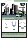
Incorrect positioning of the antennas and recei-
ver is just as frequently a source of undesirable
interference. It is essential to ensure a mini-
mum distance of 5 feet (1.5 m) from large
metal objects such as lighting gantries and
stage decorations (especially wire mesh). You
should also avoid placing antennas in wall
niches to prevent shadowing. Radio signals
reflected or shadowed by walls, ceilings or
metal structures also weaken the useful signal,
thus resulting in improper functioning of the
radio equipment (see WMS 40 illustration on
page 6/7). The interference from electrical
appliances that cause electrosmog (such as
computers and lighting equipment) can be par-
ticularly disturbing during deep fades. During a
deep fade that changes only slowly, a tone code
squelch prevents unwanted noise from lasting
too long.
On the other hand, a conventional muting cir-
cuit is unable to differentiate between “friend”
(the right frequency) and “foe” (unwanted sig-
nals). If the level of interference is too high, it
may interrupt the audio path during noisy deep
fades. Most receivers use both types of circuit:
a fast muting circuit to eliminate short bursts of
noise, and a tone code squelch to reject persis-
tent noise. Since both types of circuit act like a
hard gate on the audio signal, there will always
be some residual switching noise.
To ensure problem-free operation, always ob-
serve the following basic rules when setting up
a multichannel wireless system as opposed to a
single channel application. Always position the
receiving antennas within the far-near differ-
ence range (see page 45). Nevertheless, make
sure there is always an unobstructed line of
sight between the transmitter and receiver
during the performance. Also, the better the
audio signal fed to the transmitter and the high-
er the signal/noise ratio of the transmitter and
receiver, the better your wireless system will
work. Basically you should always set the trans-
mitter audio input gain first. The signal-to-noise
ratio is the ratio between the amplitude of the
wanted signal and the noise amplitude; it is a
logarithmic expression for the purity of a signal.
With radio transmission, the signal/noise ratio
depends on the amplitude of the audio signal.
The stronger the audio signal, the better the sig-
nal-to-noise ratio. This is why it is always a good
idea to make sure not to set the audio input
gain of the transmitter too low.
In order to enhance the signal/noise ratio, the
audio signal passes through a pre-emphasis cir-
cuit in the transmitter and a corresponding de-
emphasis circuit in the receiver. The amplitude
of the signal is not evenly distributed over the
frequency spectrum. Higher frequencies have a
lower amplitude than lower frequencies, resul-
ting in a lower signal-to-noise ratio for higher
frequencies than for lower ones. FM demodula-
tion generates more high-frequency noise. The
pre-emphasis circuit boosts higher frequencies
ahead of the radio link, whilst the de-emphasis
circuit in the receiver attenuates them by a cor-
responding amount.
AKG WMS MULTICHANNEL TECHNOLOGY