


86 www.akg.com
DEFINITIONS FROM A TO Z
GLOSSARY
Antenna Cable
Cable specifically designed for RF signals.
Used for connecting a remote antenna to a
receiver. Antenna cables are typically coaxi-
al and symmetrical. Signal attenuation de-
pends on the frequency band of the signal
as well as the length and quality of the
cable and is quoted for a 100-m run of
cable.
Antenna Splitter
Electronic network specifically designed for
RF signals. Distributes an antenna output
signal to several receivers. Powered anten-
na splitters use an amplifier to compensate
for cable attenuation while passive antenna
splitters have no amplifier.
Balanced/Unbalanced Connections
Microphones can be connected to an
amplifier with either balanced or unbalan-
ced cables. In a balanced cable, the signal
is carried by the two inner conductors and
the shield is not part of the signal path.
Even with long cable runs, any external in-
terference signal (such as power line hum)
would be induced equally in both conduc-
tors and thus be canceled. Unbalanced
cables use only one center conductor as the
“hot” wire, the shield being the ground
(“cold”} lead. While this arrangement
works well with cables up to 10 meters in
length low-frequency, long-wave hum inter-
ference may be picked up by longer cables
which act as a long-wave antenna.
BNC
Connector specifically designed for RF lines.
Booster
Amplifier for RF signals. Boosters are
connected between a transmitter output
and the antenna in order to increase radia-
ted power (custom product).
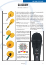
Condenser Microphone
The transducer element consists of a vibra-
ting diaphragm (metalized foil) only about
a ten thousandth of an inch thick and a
fixed metal electrode (back plate). The two
electrodes make up a capacitor (condenser)
charged by an externally applied DC volta-
ge 1" polarizing voltage or carrying its own
permanent charge. The sound waves dri-
ving the diaphragm will vary the capaci-
tance of the capacitor and consequently
the microphone output voltage will vary in
step with the sound waves.
Condenser microphones, also called “capa-
citor microphones”, need an impedance
converter (preamplifier) to match the very-
high-impedance condenser transducer to
low-Z inputs. Condenser microphones
usually have a flat frequency response,
high sensitivity, and good transient res-
ponse. They require a power supply. All AKG
condenser microphones are designated by
the letter(s) “C” or “CK” in front of the
model number.
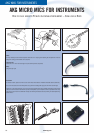
Connecting AKG Microphones
All handheld microphones listed in this
catalog are low-impedance 1200 to 620
incorporating a balanced output on a 3-pin
male XLR connector. Conforming to IEC
268-12, pin 1 is ground, pin 2 high, and
pin 3 low. The output is compatible with all
mixers, tape recorders, etc.
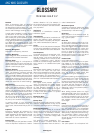
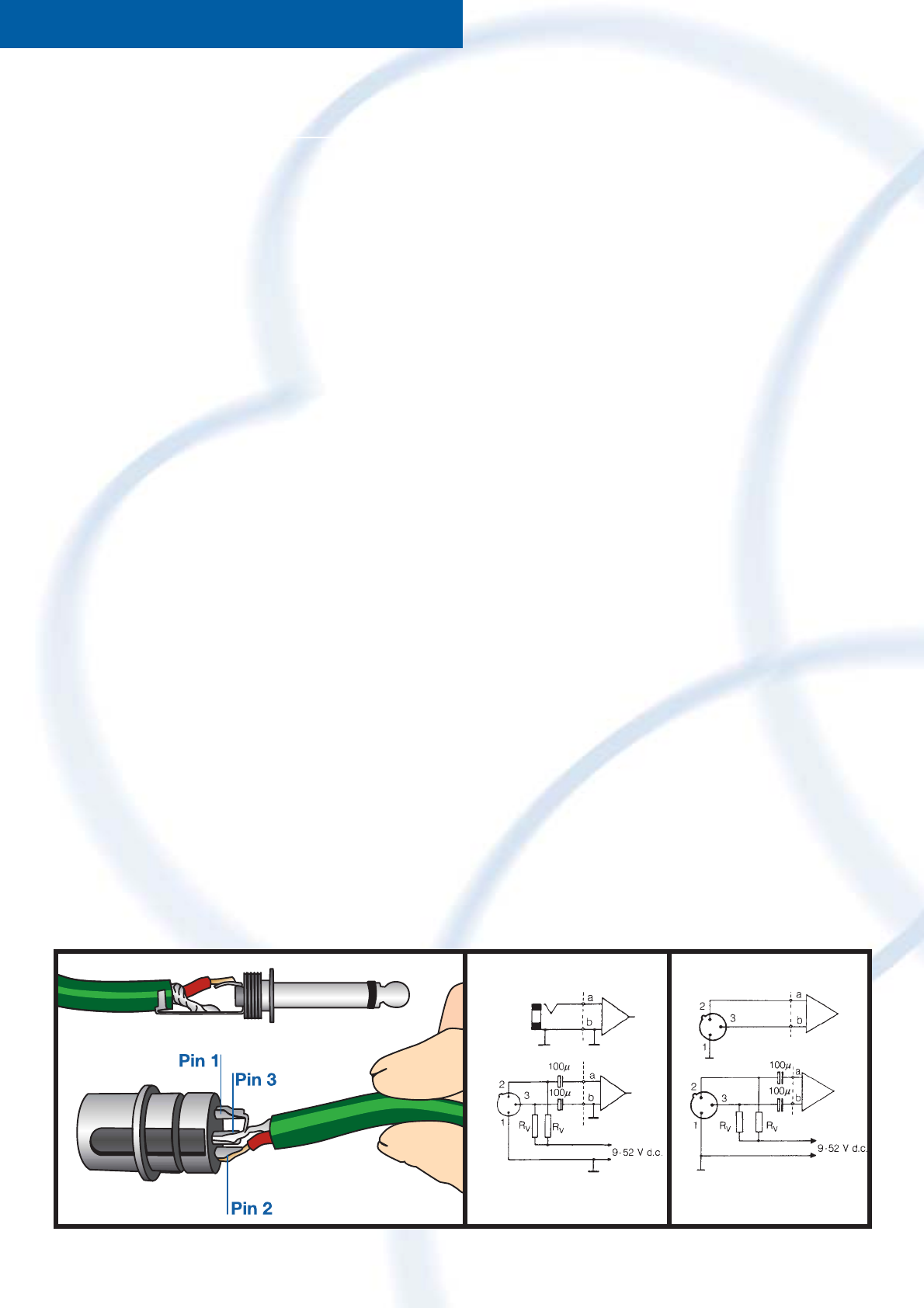
To connect an AKG microphone to an input
jack, wire the microphone cable as follows:
connect the sleeve of the jack plug
(ground) to the cable shield and the shield
to pins 1 and 3 on the XLR connector. The
center (“hot”) wire connects pin 2 to the
jack plug tip (see diagram1).
If your installation uses pin 3 as “high” or
“hot”, bridge pins 1 and 2 for unbalanced
connections and make sure to follow the
same convention for all cables in order to
avoid phase reversal problems.
Very old sound systems sometimes have
high-impedance microphone inputs.
Should the signal of a low-impedance mic-
rophone be too weak, insert a 1:10 step-up
transformer at the amplifier input. Long
cable runs used with high-impedance
equipment cause high-frequency loss. The
same applies if you connect a microphone
to a high-impedance guitar amplifier input.
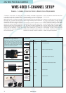
Connecting Condenser Microphones
Condenser microphones - except for the
battery powered C 1000 S - require an ope-
rating voltage that needs to be fed through
the microphone cable (phantom powering).
This can be done in several ways:
1. From a mixer with built-in phantom
power (9 to 52 V).
2. By modifying the mixer or tape recorder
to provide phantom power: find a regu-
lated DC voltage between 9 and 52 V in
the power supply. All modern AKG con-
denser microphones accept any voltage
within this range. Wire the input(s) as
shown. Current consumption of the
phantom circuit is negligible (about
1 mA per mic). Replace the input jacks
with XLR sockets if possible. While ste-
reo jacks will work as well, there may be
a risk of mistaking them for send/returns
or the like.
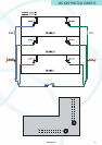
Use the following standard resistances (IEC
26815) for Rv:
Voltage Resistance
12 V (±2 V) 680 Ω +10%
24 V (±4 V) 1.2 kΩ ±10%
48 V (±4 V) 6.8 kΩ ±10%
Make sure to use resistor pairs whose com-
bined actual value is within 0.4 % of the
specified value!
3. By inserting N 62 E or N 66 E AC power
supplies between the mixer and micro-
phones.
4. By using the B 18 battery power supply
which is ideal for outdoor recording.
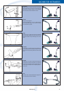
Unbalanced Input jack
Balanced Input
XLR Socket
Modified Input with
phantom powering
Modified Input (XLR) with
phantom powering
➀➁➁
AKG WMS GLOSSARY