


American Audio would like to thank for your
purchase of this great product. For those of
you that are to impatient to read the entire user
manual we have compiled these quick start
instructions. We hope that you will at least read
through these instructions to familiarize your-
self with the basic understanding of the unit.
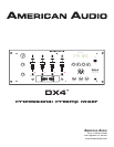
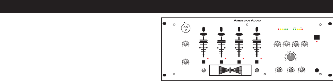
The DX4™ is part of American Audio’s continu-
ing evolution in audio technology. This unit has
been built and designed with the typical DJ in mind, by DJ’s. We have attempted to provide you with
the most reliable product on the market by using only components made from quality products.
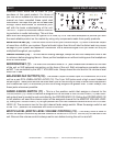
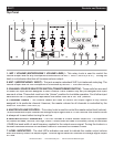
MASTER LEVEL (5) -
Use this level control to set your volume output. Try never to send an output
of more than +4dB to your system. Signal at levels higher than this will start to distort and may cause
damage to your system and speakers. Remember that a distorted signal from you mixer will only be
multiplied throughout your system.
HEADPHONES (16) -
To avoid sever hearing damage, always be sure the headphone level is set
to minimum before plugging them in. Never put the headphone on without making sure the headphone
level is turned down.
MICROPHONE 1 (1) -
The main mic connector uses a 1/4” jack unbalanced connector on the rear
of the unit or XLR balanced connection on the face of the unit. Both microphone connection marks
as MIC 1 are controlled by the MIC 1 VOLUME knob. Always leave the mic level to it’s minimum level
when not in use.
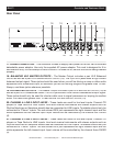
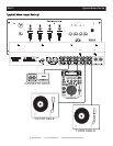
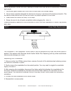
BALANCED XLR OUTPUTS (18) -
The Master Output includes a pair XLR Balanced
JACKS
as
well as a pair
RCA UNBALANCED JACKS (19).
The 3-pin XLR jacks send a high current balanced
output signal. These jacks should be used when you will be driving an amp or other audio equipment
with a balanced input, or whenever you will be running a signal line greater than 15 feet. Always, use
these jacks whenever possible.
FADER ASSIGN SWITCH (11) -
This is a five position switch that assigns a channel to the
CROSSFADER (12)
. When a channel is assigned to the left side of the
CROSSFADER (12)
that chan-
nels output level is routed to and controlled by the
CROSSFADER (12)
. Sliding the
CROSSFADER (12)
to left position will send the volume output of the assigned channel to the
MASTER VOLUME LEVEL
(5)
, siding the
CROSSFADER (12)
to right position will cut that channels volume to
MASTER VOLUME
LEVEL (5)
.
The reverse is true for the right channel fader assign switch. When the assign switch is set
to the "OFF" position the crossfader will have no function.
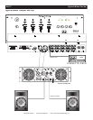
BOOTH LEVEL (BOOTH LEVEL VOLUME CONTROL) (13) -
This rotary knob is used to
control the output volume to any source connect to the
BOOTH OUTPUT JACKS (25)
on the rear of the
unit. Be sure this volume control is always set to zero before turning the unit on and off.
DX4™ QUICK START INSTRUCTIONS
©
American Audio
®
- www.americandj.com - DX4™ Instruction Manual Page 4
M
I
C
1
L
I
N
E
1
P
H
O
N
O
1
L
I
N
E
2
P
H
O
N
O
2
L
I
N
E
4
L
I
N
E
3
L
I
N
E
6
L
I
N
E
5
C
U
E
C
U
E
C
U
E
C
U
E
M
I
C
1
V
O
L
U
M
E
1
0
0
BASS
100
MIDLOW
100
MIDHIGH
100
TREBLE
100
LEFT
+5
0 -5-10 -15
MASTERLEVEL
MASTER
LEVEL
10
0
BOOTH
LEVEL
10
0
CUE
MIXING
PGM
CUE
CUE
LEVEL
10
0
PHONES
POWER
MIC2
VOLUME
10
0
5
5
5
5
5
5
5
5
ASSIGNCH
ASSIGNCH
RIGHT
-15
-10 -5 0 +5