


Color 150/RG™ Operation
©American DJ Supply® - www.americandj.com - Color 150/RG™ Instruction Manual Page 8
Note: Stand-Alone and Master-Slave operation require sound to acti-
vate! The units will blackout in this mode to conserve bulb life when
there is no sound present.
Stand-Alone Operation (Sound Active): This function allows a
single unit to run to the beat of the music. Only use this function when
running a single unit, or when running several units as individuals.
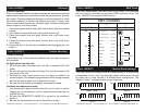
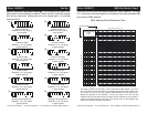
1. To activate the Sound-Active mode, set dip switch 10, on the
rear of unit to the ON position (See “Master Unit” on the DIP
SWITCH chart on page 15).
2. The unit will now react to the low frequencies of music via the inter-
nal microphone.
3. Adjust the audio sensitivity knob on the rear of the unit to make the
unit more or less sensitive to sound. Turning the sensitivity knob in
the clockwise direction will increase the sensitivity, turning the knob
in the counter-clockwise direction will decrease the fi xture’s sensi-
tivity to sound.
4. The optional MINI/C Blackout Controller may be used with this
function. This controller is used for blackout function only.
Master-Slave Operation (Sound Active): This function will allow
Color 150/RG™ Operation
©American DJ Supply® - www.americandj.com - Color 150/RG™ Instruction Manual Page 7
you to link up to 16 units together and operate without a controller. The
units will be sound activated. In Master-Slave operation one unit will act
as the controlling unit and the others will react to the controlling units
programs. Any unit can act as a Master or as a Slave.
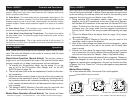
1. Using standard XLR microphone cables, daisy chain your units
together via the XLR connectors on the rear of the units. Remem-
ber the Male XLR connector is the input and the Female XLR is the
output. The fi rst unit in the chain (master) will use the female XLR
connector only. For longer cable runs we suggest a terminator at
the last fixture. Refer to the set-up procedures beginning on page
10.
2. Follow the Master-Slave dip-switch chart on page 16 for proper
dip-switch settings.
3. The optional MINI/C Blackout Controller may be used in this
operation mode to control the blackout.
4. After all the units settings have been set and are plugged in, adjust
the sensitivity knob on the rear of the master unit to make them
react to sound.
5. Several unit may share the same slave setting as long as there
are no more than 16 units in a Master-Slave confi guration, however
only one unit may have the “Master - Head 1” dip switch setting.
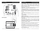
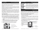
11. Cooling Fan - This fan is used to keep the unit operating at a cooler tem-
perature. Keep the fan grill clean. Never block the grill, improper cooling may
result in premature lamp failure.
12. Gobo Wheel - This wheel holds the two replaceable rotating gobos. The
gobos are 26mm (20mm viewable). For list of stock replaceable gobos contact
customer support or visit us on the web. Custom gobos may be order through
customer support. Please contact customer support for a quote on all custom
gobos.
13. Gobo Wheel Cover - This protective cover shields the gobo wheel. To
access and change the gobos remove this cover.
14. Gobo Wheel Cover Retaining Thumb Screw - This thumb screw retains
the gobo wheel cover. To access the gobo wheel remove this screw and the
gobo wheel cover.
15. Fully Focusing Lens - This is high quality lens that is fully focusing. To
focus this lens, turn the lens in clockwise and counter-clockwise direction until
you achieve proper focus.
Color 150/RG™ Controls and Functions
Linking: Your fi xture comes with several built-in programs. These pro-
grams are designed to work with up to 16 units when daisy-chained
together in a master-slave confi guration. Any unit can function as either
a “Master Unit” or a “Slave Unit.” Link the units together using standard
DMX cable.
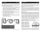
For a more dramatic effect, link several Color units together.
To next Color 150/RG™ if applicable
Master/Slave Linking:
Optional MINI/C blackout controller