


©American DJ Supply® - www.americandj.com - Color 150/RG™ Instruction Manual Page 10©American DJ Supply® - www.americandj.com - Color 150/RG™ Instruction Manual Page 9
Color 150/RG™ Set Up
Universal DMX Control: This function allows you to use a universal
DMX 512 controller such as the American DJ
® DMX Operator™ or
Show Designer™ to control lamp intensity, color, and gobo. Operating
through a DMX controller allows the freedom to create unique pro-
grams tailored to one’s individual needs.
1. The Color 150/RG™ uses three DMX channels. Channel one con-
trols the lamp intensity (dimmer), channel two controls the color
selection, and channel three control the gobo wheel. Please refer
to page 15 for a detailed description of the DMX traits.
2. To control your fixture in DMX mode, follow the unit set-up proce-
dures beginning on page 10 as well as the set-up specifications
that are included with your DMX controller.
3. Use the controller’s faders to control the various DMX fixture traits.
4. This will allow you to create custom programs.
5. When using a DMX controller and setting up for DMX operation
follow the dip switch settings on page 15.
6. For help operating in DMX operation consult the manual included
with your DMX controller.
7. For longer cable runs (more than a 100 feet) use a terminator on
the last fixture in you DMX chain.
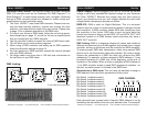
Color 150/RG™ Operation
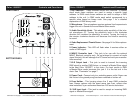
To next DMX unit or terminate.
DMX Linking:
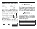
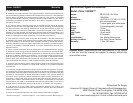
Power Supply: Before plugging your unit in, be sure the source
voltage in your area matches the required voltage for your American
DJ
® Color 150/RG.™ Because line voltage may vary from venue to
venue, you should be sure your unit voltage matches the wall outlet
voltage before attempting to operate you fi xture.
DMX-512: DMX is short for Digital Multiplex. This is a universal
protocol used as a form of communication between intelligent fixtures
and controllers. A DMX controller sends DMX data instructions from
the controller to the fixture. DMX data is sent as serial data that
travels from fi xture to fi xture via the DATA “IN” and DATA “OUT” XLR
terminals located on all DMX fi xtures (most controllers only have a
DATA “OUT” terminal).
DMX Linking: DMX is a language allowing all makes and models of
different manufactures to be linked together and operate from a single
controller, as long as all fi xtures and the controller are DMX compliant.
To ensure proper DMX data transmission, when using several DMX
fixtures try to use the shortest cable path possible. The order in which
fixtures are connected in a DMX line does not influence the DMX
addressing. For example; a fixture assigned a DMX address of 1 may
be placed anywhere in a DMX line, at the beginning, at the end, or
anywhere in the middle. When a fixture is assigned a DMX address of
1, the DMX controller knows to send DATA assigned to address 1 to
that unit, no matter where it is located in the DMX chain.
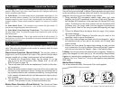
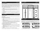
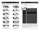
Dip-switches in DMX mode: This unit uses dip switches to assign a
DMX address. Each dip switch represents a binary value.
Dip Switch 1 address equals 1
Dip Switch 2 address equals 2
Dip Switch 3 address equals 4
Dip Switch 4 address equals 8
Dip Switch 5 address equals 16
Dip Switch 6 address equals 32
Dip Switch 7 address equals 64
Dip Switch 8 address equals 128
Dip Switch 9 address equals 256
Each dip switch has a preset value. A specific DMX address is set by
combining the dip switches that sum your desired value. For example:
ON
198765432 10
12828 32
256651641
SP
DMX CHANNEL