


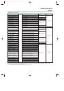
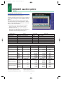
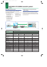

Waveform pattern Uplink / Downlink Data Output slot Communications
GMSK_PN9 Uplink / Downlink
––
8PSK_PN9 Uplink / Downlink
––
GMSK_TN0 Uplink / Downlink TN0
–
8PSK_TN0 Uplink / Downlink TN0
–
NB_TN0 Uplink / Downlink TN0
NB_ALL Uplink / Downlink All slot
TCH_FS Uplink / Downlink TN0 GSM
CS-1_1SLOT Uplink / Downlink TN0
CS-4_1SLOT Uplink / Downlink TN0
DL_MCS-1_1SLOT Uplink / Downlink TN0
UL_MCS-1_1SLOT Uplink / Downlink TN0
GPRS
DL_MCS-5_1SLOT Uplink / Downlink TN0
UL_MCS-5_1SLOT Uplink / Downlink TN0
DL_MCS-9_1SLOT Uplink / Downlink TN0
EDGE
UL_MCS-9_1SLOT Uplink / Downlink TN0
DL_MCS-9_4SLOT Uplink / Downlink TN0, 1, 2, 3
UL_MCS-9_4SLOT Uplink / Downlink TN0, 1, 2, 3
11
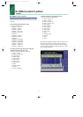
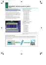
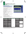
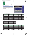
GSM/EDGE waveform pattern
Standard
■ GSM/EDGE waveform pattern:
The GSM/EDGE waveform patterns listed in the table below
are provided on the MG3700A internal hard disk.
The signals suitable for testing receivers and for managing
device evaluation in a GSM/EDGE system can be output by
selecting one of these GSM/EDGE waveform patterns.
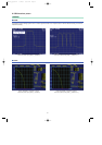
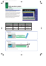
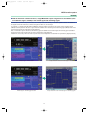
•
GMSK_PN9, 8PSK_PN9
PN9 data is inserted into the entire area of the slots, except the
guard. The PN9 data in each slot are continuous.
•
GMSK_TN0, 8PSK_TN0
PN9 data is inserted into the entire area of the slots, except the
guard. The PN9 data in each slot are continuous.
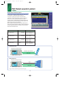
•
NB_TN0, NB_ALL
PN9 data is inserted into the normal burst encrypted bit area.
The PN9 data in the slots are continuous.
•
TCH_FS
Supports the Speech channel at the full rate (TCH/FS) specified
in Section 3.1 of 3GPP TS05.03.
•
CS-1_1 (4)_SLOT (_4SLOT )
Supports the packet data block type 1 (CS-4) and 4 (CS-1)
specified in Section 5.1 of 3GPP TS05.03.
•
DL (UL)_MCS-1 (5, 9)_1SLOT (_4SLOT)
Supports the packet data block types 5(MCS-1), 9(MCS-5), and
13 (MCS-9) specified in Section 5.1 of 3GPP TS05.03.
∗
1: PN9 data is inserted into the entire area that does not have the slot format.
∗
2: PN9 data is inserted into the entire area of the slots, except the guard.
∗
3: PN9 is inserted into the normal burst encrypted bit area.
∗
4: The bit string channel-coded for PN9 data is inserted into the normal burst encrypted bit area.
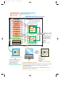
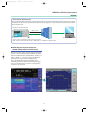
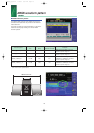
Example of selecting waveform pattern
PN9
∗
3
PN9
∗
4
PN9
∗
1
PN9
∗
2
*MX370X_E_050127 1/28/05 8:50 AM Page 11