


13
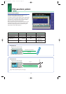
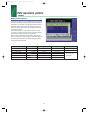
PDC waveform pattern
Standard
■ PDC waveform pattern:
The waveform patterns for the wanted signals/interfering signals
required to execute transmission/reception tests as specified in
ARIB STD-27 are provided on the MG3700A internal hard disk.
Modulation signals conforming to the standard can be output
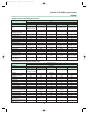
without any options (Note: Check the parameters listed on the
next page in advance).
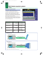
The waveform pattern to output uplink/downlink Slot 0 data
only and the unframed waveform pattern for interfering signals
are provided for full rate and half rate, respectively.
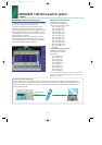
When a signal is required that has parameters different from
those of the provided waveform patterns, parameter setting and
waveform pattern generation are available using the optional
MX370102A TDMA IQproducer.
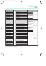
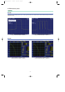
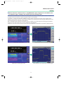
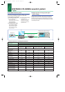
Example of selecting waveform pattern
Waveform pattern Uplink / Downlink Half rate / Fill rate Output slot Evaluation
PI_4_DQPSK_PN9
——
No frame TX device test
PI_4_DQPSK_PN15
——
No frame Interfering signal
DL_Full_Rate_Slot0 Uplink / Downlink Full rate Slot 0 only
DL_Half_Rate_Slot0 Uplink / Downlink Half rate Slot 0 only Wanted signal for
UL_Full_Rate_Slot0 Uplink / Downlink Full rate Slot 0 only receiver test
UL_Half_Rate_Slot0 Uplink / Downlink Half rate Slot 0 only
*MX370X_E_050127 1/28/05 8:51 AM Page 13