


14
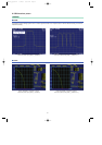
PDC Packet waveform pattern
Standard
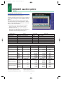
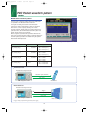
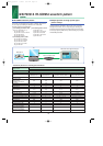
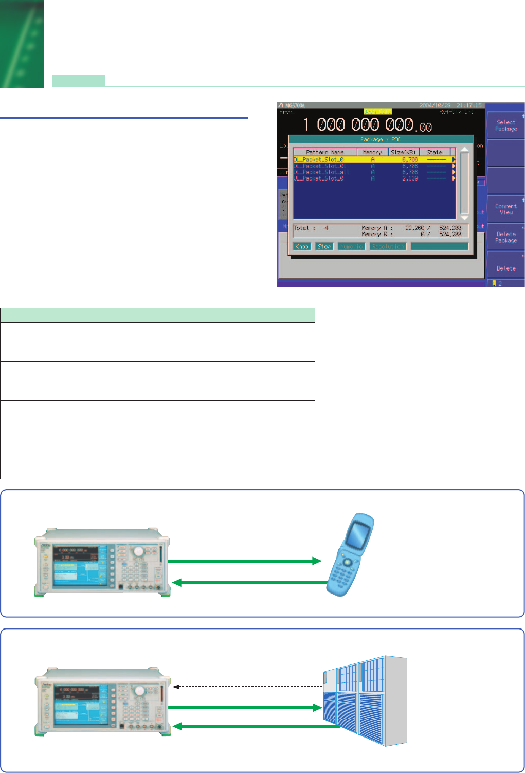
■ PDC Packet waveform pattern:
The four types of waveform patterns listed in the table below
are provided on the MG3700A internal hard disk.
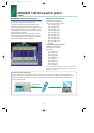
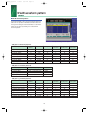
The signals for testing base station and mobile station
receivers for UPCH communications, which are specified in
RCR STD-27, can be output by selecting one of these
waveform patterns, without setting any complex RCR STD-27
parameters. Also, the Downlink3 data rate UPHC pattern and
Uplink1 UPHC pattern can be switched.
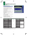
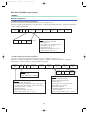
When a signal is required that has parameters different from
those of the provided waveform patterns, parameter setting and
waveform pattern generation are available using the optional
MX370102A TDMA IQproducer.
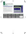
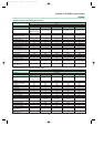
Example of selecting waveform pattern
Waveform pattern Uplink / Downlink Output slot
Slot 0 = UPCH
DL_Packet_Slot_0 Uplink / Downlink Slot 1 = IDLE (all "1")
Slot 2 = IDLE (all "1")
Slot 0 = UPCH
DL_Packet_Slot_01 Uplink / Downlink Slot 1 = UPCH
Slot 2 = IDLE (all "1")
Slot 0 = UPCH
DL_Packet_Slot_all Uplink / Downlink Slot 1 = UPCH
Slot 2 = UPCH
Slot 0 = UPCH
UL_Packet_Slot_0 Uplink / Downlink Slot 1 = Transmit off
Slot 2 = Transmit off
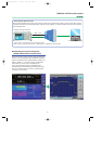
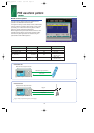
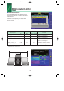
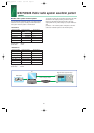
•
Mobile station test
MG3700A Vector Signal Generator
Modulation signal (Downlink)
Data, Clock
BER analyzer is built in.
Mobile device
Base station
•
Base station test
MG3700A Vector Signal Generator
BER analyzer is built in.
Modulation signal (Uplink)
Data, Clock
Tr igger
∗
∗
Trigger: Timing for synchronizing sub frames (frame trigger)
*MX370X_E_050127 1/28/05 8:51 AM Page 14