


Installation Manual
4
2.
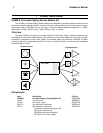
Connection to the Telephone System
General Instructions
This section contains installation procedures for connection to the telephone system. You should
first follow the General Instructions and then refer to the Specific Instructions for the type of telephone
switch to be connected (loop- or ground-start trunk port, station port, page port). Finally, refer to Section
3 for connections to the paging system.
You will need the following tools for installation: standard flat-blade screwdriver; phillips-head
screwdriver; wire cutter/stripper/crimper; punch-down tool for Type 66 Block.
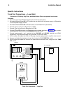
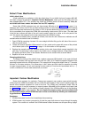
Select location and physical installation
The UPAM may be mounted on a wall or backboard. It can be located either in close proximity to
the telephone equipment (a modular cord is included and can be used to connect the unit to the telephone
system) or near the paging equipment. To install the unit using the keyhole slots, install two screws (not
included) with a 7-½" center, letting the screw heads protrude ¼" from the wall. Position the unit on the
screws through the slots then tighten the screws. A 110V AC outlet should be located nearby when using
the UPAM with trunk port equipment.
Grounding
The UPAM is designed with protection devices which are intended to shunt to ground any excess
(surge) voltage appearing on the
T
ip
and
R
ing input pair. The metal case of the UPAM must be grounded
to a ground shorting bar, if available, or to a suitable electrical (earth) ground. Connect a ground wire
(with a fork-terminal, included) between the case and the screw on the lower left-hand corner of the
module. An external-tooth lockwasher ensures a good connection between the case and ground terminal.
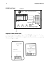
Mode switches
A set of 5 mode switches (S1 through S5, see the illustration on the previous page) is included
to set the power supply voltage, confirmation or preannounce tone, and VOX operation. These switches
are accessible through an opening in the front cover and can be moved with a pointed tool, such as the
tip of a ball point pen. Set the switches as described in the Specific Instructions, which follow.
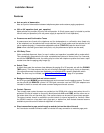
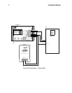
Power supply connections
No power supply is required when the UPAM is connected to a PABX station port (supplying analog
ring voltage and approximately 48-volt of Talk Battery) or Centrex line. One of two types of power supply
is included in the UPAM-K. You can identify the power supply from the illustration on page 3. Note the
location of the output terminals; they are not in the same order. Either supply will power the UPAM
and provide 48 volt talk battery for trunk port or page port operation. The illustrations in the Specific
Instructions section show the correct connections from a typical power supply to the UPAM module.
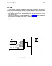
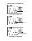
Internal adjustments
Certain options are available (described in Specific Instructions section) which require the removal
of the cover and the modification of certain components. The illustrations on page 11 show the different
revision levels of the printed circuit boards used, and identify the location of the important components.
A small parts bag is located under the cover, either taped to the inside of the cover or wedged
between the case and a large capacitor in the upper right-hand corner of the chassis.
Paging system connections
Illustrations showing connection of the UPAM to a typical paging system are included in the third
section of this manual. If you need more information about paging systems, consult the UPAM CPE
Reference Guide, available from AT&T.
Troubleshooting
A Functional Test Guide in Section 4 isolates problem areas, if they arise, following installation.