


GENERAL WIRING PRACTICE
Assembly of the Stereo 35 is exceptionally simple when
compared to that the other kits. The circuit board are sup-
plied with all components mounted, and the remaining parts
arranged on the chassis in an open, uncluttered way that
makes wiring quick and easy. The construction of the Stereo
35 should take no more than few hours.
When you unpack the kit, check the components against
the parts list first. You can identify unfamiliar components
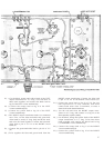
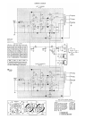
by matching them to parts illustrated in the pictorial
diagram supplied.
Have the proper tools at hand before beginning to build
your kit. You will need a pencil-type soldering iron of 30-
to 60-watt rating; a long-nosed pliers; diagonal cutters; and
a screwdriver. If you have a soldering gun, it should be used
with care, especially when working on the circuit board,
because of its higher than necessary heat output. Although
not essential, a wire-cutting and stripping tool will help
considerably; these are available for less than a dollar.
The only procedure involved in building a Dynakit
which requires a bit of technique is soldering, and this is
quite easy to master. There are four steps to making a good
solder connection:
1. Make a good mechanical connection.
2. Heat both parts of the connection with the iron.
3. Apply solder to the connection until it melts and
runs.
4. Allow the connection to cool undisturbed.
ALL SOLDERING MUST BE DONE WITH ROSIN
CORE SOLDER.
There is no warranty on any equipment in which acid
core solder has been used. Make sure that the solder you
use is plainly marked "Rosin Core". If you have solder on
hand of doubtful origin, it is wise to obtain a new roll of
50/50 or 60/40 rosin core solder.
Whenever a connection is to be soldered, the instructions
indicate this by the symbol (S). If this symbol is not
shown after a step, further connections must be made to
the same point before soldering.
A number of steps in the instructions begin,"Connect
one end of a wire...", with the length of the wire specified.
In each case, first cut a piece of wire to the correct length
from the roll supplied with the kit and then remove about
¼" of insulation from each end before making the connec-
tion. The leads on components should be trimmed as they
are used, the length chosen being that
which permits a con-
nection to be made from point to point without strain on
terminals or components. The lead "dress", that is the
manner in which the wiring is arranged as it goes from one
point to another, should follow that shown in the pictorial
diagram as closely as possible. Care must be exercised to
see that uninsulated wires do not touch each other, and
cannot do so through vibration or sagging, unless of course,
they are connected to the same point. It is especially impor-
tant that uninsulated wires and component leads or ter-
minals do not touch the chassis or bottom plate accidentally.
Check your work after each step, and, when you are sat-
isfied that it has been correctly done, mark the space pro-
vided and go on to the next step. Examine the pictorial
diagrams often; if you check your work methodically, your
amplifier should work as soon as the wiring is complete.
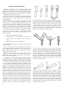
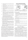
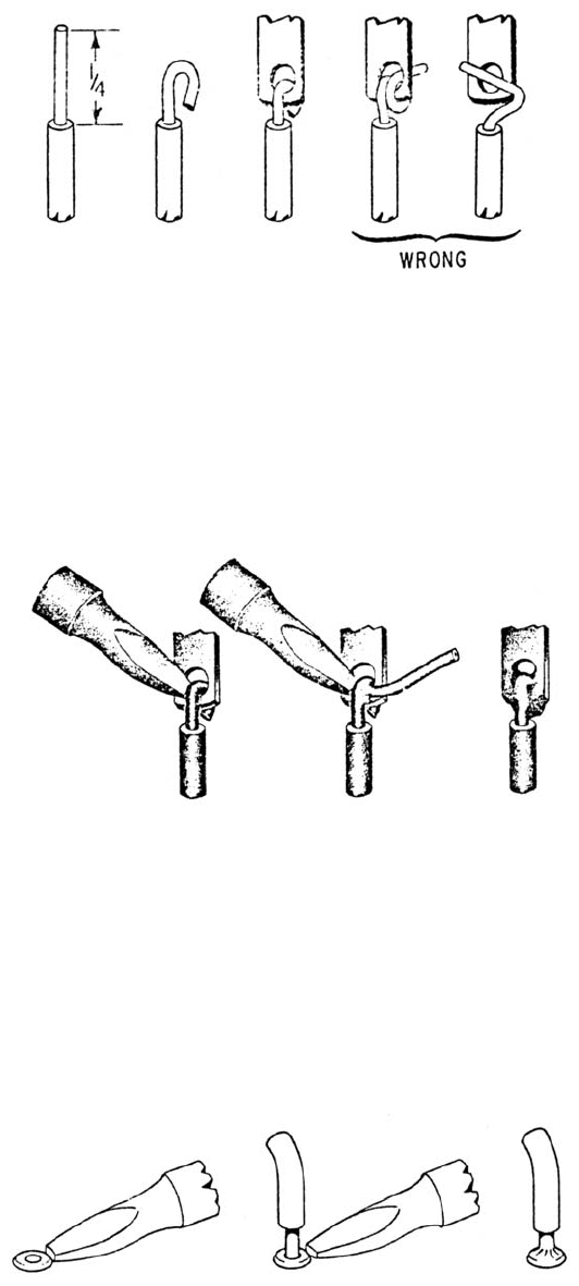
One of the best ways to make a good mechanical connection
is to bend a small hook in the end of the wire, and then to
crimp this hook onto the terminal to be connected. The
amount of bare wire exposed at the end need to be exactly
¼-inch; however, if it is too long, there is danger of the
excess touching another terminal or the chassis. There is
no need to wrap the wire around the terminal more than
one time, as this makes a connection that is much more
difficult to remove if an error has been made
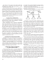
To transfer heat from the iron to the wire and terminal,
the tip of the iron should be kept brightly tinned with
solder. If this is properly done the first time the iron is
used, the tinning may be maintained by wiping the tip with
a cloth or sponge every few minutes while soldering. When
correctly tinned, the tip will heat both parts of the con-
nection almost immediately. Solder should then be applied
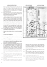
directly to the parts to be soldered. as shown in the middle
illustration above, and both iron and solder removed as
soon as the solder flows freely.
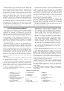
The circuit boards of the Stereo 35 are supplied with all
components (resistors and capacitors) already mounted
and soldered in place. The circuit boards are connected to
the other sections of the amplifier channels by soldering
wires to eyelets on the boards. These eyelets, which are
numbered for identification, are filled with solder already.
To solder a wire to them, they are first heated with the tip
of the iron, and the end of the wire inserted as soon as the
solder in the eyelet flows. A correctly made connection looks
like the illustration at the right, above, which shows a smooth
transition from eyelet to wire.
4