


9
53( ) Connect one end of a 1¼" wire to pin #9 of V-3 on
the LEFT circuit board (S). Connect the other end
to eyelet #11 (S).
54 ( ) Connect one end of a 1" bare wire to pin #2 of V-3
on the LEFT circuit board (S). Connect the other
end to eyelet #9 (S).
55( ) Connect one end of another 1" bare wire to pin #2
of V-2 on the LEFT circuit board (S). Connect the
other end to eyelet #8 (S).
56( ) Connect one end of a 1" wire to the long lug of the
LEFT input socket (S). Connect the other end to
eyelet #1 (S).
57( ) Connect one end of a 1
½" wire to the short lug of
the LEFT input socket (S). Connect the other end
to eyelet #2 (S).
58( ) Insert the line cord through the rubber grommet
mounted on the chassis, and push it through far
enough to tie a knot about 5" from the end. Tie the
knot. Then separate the two conductors of the line
cord for about 4". Cut 1½" from one of them, and
strip and tin the ends of both.
59( ) Connect the longer of the two line cord conductors
to lug #4 of the 5-lug terminal strip (S). Connect
the other conductor to lug A of the fuse holder (S).
This completes the wiring of the Stereo 35.
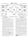
PLACES TO DOUBLE CHECK AFTER WIRING
( ) Be sure that all mounting screws and nuts are tight.
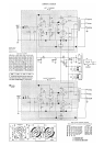
( ) Compare the wiring of each of the tube sockets to that
shown in the pictorial diagram. All connections should
securely soldered, with enough space between con-
nections to the tube pin lugs so that there is no chance
of an accidental short-circuit.
( ) Compare the wiring to each lug of the filter capacitor
with that shown on the diagram. Check carefully to see
that all connections are soldered, and that excess lead
length has not caused any connection to short-circuit
to the chassis. Count the wires going to each terminal
on diagram and amplifier.
( ) Use special care in examining all connections, to be sure
that none of them are high enough to touch the bottom
plate when it is installed. Check the 5-lug terminal
strip and filter capacitor closely.
The tubes and fuse may now be installed. The socket on
each board which is supplied already mounted is for the
7247 tube. Each of the two sockets installed and wired
during assembly receives one of the 6BQ5 tubes. IMPOR-
TANT: When inserting the tubes in their sockets for the
first time, the socket should be supported from below to
avoid strain on the circuit board, due to the tight fit of new
sockets. The amplifier a.c. cord should NOT be plugged
into a wall outlet until after the tubes are installed, and
the cover and bottom plate are securely in place.
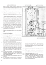
The cover and bottom plate are attached at the same
time, by setting the amplifier chassis on the bottom plate,
which fits inside the chassis, and then lowering the cover
onto the chassis. The three pieces are fastened together by
four sheet metal screws through the sides of the chassis. The
four rubber feet are installed by pressing them into the
corner holes of the bottom plate. The cover should be used
whenever the amplifier is operated where it may be touched
accidentally; not only do the tubes become quite hot in
operation, but some point on the circuit board carry a
voltage which, while non lethal, can be quite uncomfortable
if touched while the amplifier is on.
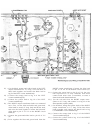
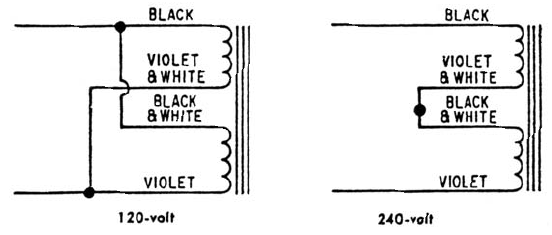
SPECIAL INSTRUCTIONS FOR OPTIONAL
120-240 VOLT POWER TRANSFORMERS
Dynakit Stereo 35 amplifiers supplied with power trans-
former PB-028 can be wired for used with either 120- or
240-volt a.c. power sources, in the following way:
For 120-volt operation.
( ) Begin with the group of seven leads from the power
transformer, all of which should come through the hole
in the chassis farthest from the fuse holder. Connect
the black lead to terminal B of the fuse holder.
( ) Connect the black-and-white lead to terminal B of the
fuse holder (S).
( ) Connect the violet lead to lug #4 of the 5 lug terminal
strip.
( ) Connect the violet-and-white lead to lug #4 of the
5-lug terminal strip.
Proceed with the wiring steps in the regular assembly
portion of this booklet, beginning with wiring step #3.
For 240-volt operation.
( ) Connect the violet-and-white lead to lug #5 of the
5-lug terminal strip.
( ) Connect the black-and-white lead to lug #5 of the
5-lug terminal strip (S).
( ) Connect the black lead to terminal B of the fuse holder
(S).
( ) Connect the violet lead to lug #4 of the 5-lug terminal
strip.
Proceed with the wiring steps in the regular assembly
portion of this booklet, beginning with the wiring step #3.
INSTALLING THE STEREO 35
In addition to the Stereo 35, your complete stereo system
will include one or more signal source (
turntable, tuner,
tape transport), a stereo preamplifier (unless included with
the signal source), and two loudspeakers.
Installation of the Stereo 35 is simple. You will need
two shielded audio cables for the inputs (usually provided
with the preamplifier) and two
lengths of two-conductors
wire with
which to make the connections to the loudspeak-
ers. Ordinary lamp cord will do for the latter.
The Stereo 35 is designed for use with stereo preampli-
fiers which have their own power supply, such as the Dyna
PAS-3. In addition to a high level of performance, the
preamplifier should be capable of delivering a signal of
about 1 volt to drive the Stereo 35 to its full output. The
Stereo 35 a.c. line cord should be connected to a switched
auxiliary a.c. outlet on the preamplifier; in this way, it
will be turned on and off automatically when the preampli-
fier is switched on and off. Since the Stereo 35 contains its
own fuse, an outlet which is not fused may be used.