


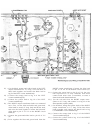
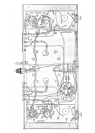

15( ) Cut the black, orange and yellow leads of the LEFT
output transformer to 3
½" long. Twist all three of
these leads together, and connect the black lead to
lug C of the LEFT 3-screw terminal strip.
16( ) Connect the orange lead to lug 8 of the LEFT
3-screw terminal strip (S).
17( ) Connect the yellow lead to lug 16 of the LEFT
3-screw terminal strip.
18( ) The RIGHT output transformer leads are connected
next. First, cut the blue-and-white and green-and-
white leads to exactly 2" long. Strip and tin the ends,
and twist the leads together. Connect the blue-and-
white lead to pin #7 of V-5 on the RIGHT circuit
board (S).
19( ) Connect the green-and-white lead to pin #9 of V-5
(S).
20( ) Twist
together the blue and green leads from the
RIGHT output transformer. Connect the blue lead
to pin #7 of V-6 on the RIGHT circuit board (S).
21( ) Connect the green lead to pin #9 of V-6. Be sure
that exposed wire or stray filaments from them
cannot touch other wires or terminals, or cause a
short-circuit to the chassis hardware.
22( ) Cut the red lead from the RIGHT output trans-
former to 4½" long, and connect it to lug #2 of the
filter capacitor (square symbol).
23( ) Cut the black, orange and yellow leads of the RIGHT
output transformer to 3½" long. Twist these three
leads
together, and connect the black lead to lug
C of the RIGHT 3-screw terminal strip.
24( ) Connect the orange lead to lug 8 of the RIGHT
3-screw terminal strip (S).
25( ) Connect the yellow lead to lug 16 of the RIGHT
3-screw terminal strip.
7