


8
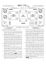
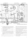
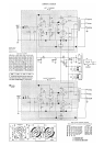
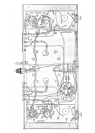
REFER TO PICTORIAL DIAGRAM #3.
26( ) Connect one end of the 6800-ohm (blue, gray, red),
1-watt resistor to lug #2 (square symbol) of the
filter capacitor. Connect the other end to lug #3
(triangle symbol) of the capacitor. The resistor leads
should be cut to permit mounting exactly as is shown
in the diagram.
27( ) Connect one end of the 50-ohm, 5-watt resistor to
lug #1 (curved line symbol) of the filter capacitor.
Connect the other end to lug #2 (square symbol)
of the capacitor (S). Check to be sure that all four
of the connections at lug #2 have been soldered,
and that excess wire has been trimmed away ,and
cannot touch the chassis or adjacent lugs.
28( ) Connect one end of the 95-ohm, 5-watt resistor to lug
#4 ( no symbol) of the filter capacitor. Connect the
other end to chassis-mounting lug B of the capacitor.
29( ) Connect one end of a 5" wire to chassis-mounting
lug B of the filter capacitor (S). Connect the other
end to lug #3 of the 5-lug terminal strip (S).
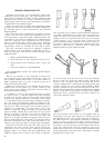
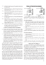
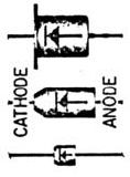
30( ) The silicon rectifier diodes supplied with the kit may
be of any of the three types shown in the illustration;
although differing in external appearance, the three
types are elettrically equivalent.
Connect the CATHODE lead of one
of the rectifier diodes to lug #1
(curved line symbol) of the filter
capacitor. Connect the ANODE lead
to lug #2 of the 5-lug terminal strip
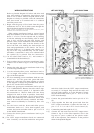
(S). IMPORTANT: Arrange the
diode leads exactly as shown in the
pictorial diagram. When soldering,
hold a pliers on the lead between the diode body and
the solder connection to avoid application of excessive
heat to the diode.
31( ) Connect the CATHODE lead of the other rectifier
diode to lug #1 (curved line symbol) of the filter
capacitor (S). Connect the other lead to lug #1 of
the 5-lug terminal strip (S). Observe the same pre-
cautions when soldering as in the preceding step.
32( ) Connect one end of a 4" wire to lug C of the RIGHT
3-screw terminal strip (S). Connect the other end
to chassis-mounting lug A of the filter capacitor.
33( ) Connect end of a 9" wire to lug C of the LEFT
3-screw terminal strip (S). Connect the other end
to chassis-mounting lug A of the filter capacitor
(S).
34( ) Connect one end of a 4" wire to lug '#3 (triangle
symbol) of the filter capacitor. Connect the other end
to eyelet #7 of the RIGHT circuit board (S).
NOTE : Before making a connection to an aye-
let on the circuit board, tin the end of the wire
by heating it with the soldering iron and touch-
ing solder to it. The wire end is tinned when
the solder melts and runs onto the wire. The
eyelets on the board already have solder in
them. To solder to the eyelet, heat it with the
soldering iron and insert the end of the wire
when the solder in the eyelet flows. Remove the
iron and hold the wire in place until the solder
hardens.
35( ) Connect one end of a 5" wire to lug #4 (no symbol)
of the filter capacitor. Connect the other end to pin
#3 of V-5 on the RIGHT circuit board.
36( ) Prepare a 1
¾" piece of wire by stripping ½" of insu-
lation from one end, and ¼" from the other end.
Push the longer bare end through pin #3 of V-6 on
the RIGHT circuit board (S), and bend it around
to connect to pin #4 of V-6 also. Connect the other
end to pin #3 of V-5 (S).
37( ) Connect one end of a 4½" wire one to eyelet #4 of the
RIGHT circuit board (S). Connect the other end
to eyelet #10 (S).
38( ) Twist together a 2½" and a 4" wire so that one pair
of end is even. Connect the matching end to pins
#4 and #5 of V-5 on the RIGHT circuit board.
Connect the shorter of the remaining end to eyelet
#5 (S), and the longer remaining end to eyelet #3
(S).
39( ) Twist together a pair of 2½" wires. Connect one
pair of ends to pin #4 (S) and pin #5 (S) of V-5
on the RIGHT circuit board. Connect the other ends
to pin #4 (S) and pin #5 (S) of V-6.
40( ) Connect one end of a 7" wire to lug 16 of the RIGHT
3-screw terminal strip (S). Connect the other end
to eyelet #6 of the RIGHT circuit board (S).
41( ) Connect one end of a 1¼" wire to pin #9 of V-6
on the RIGHT circuit board (S). Connect the other
end to eyelet #11 (S).
42( ) Connect one end of a 1" bare wire to pin #2 of V-6
on the RIGHT circuit board (S). Connect the other
end to eyelet #9 (S).
43( ) Connect one end of a 1" bare wire to pin #2 of V-5
on the RIGHT circuit board (S). Connect the other
end to eyelet #8 (S).
44 ( ) Connect one end of a 1" wire to the long lug of the
RIGHT input socket (S). Connect the other end
to eyelet #1 (S).
45( ) Connect one end of a 1½" wire to the short lug of
the RIGHT input socket (S). Connect the other end
to eyelet #2 (S).
46( ) The next group of steps are performed on the LEFT
circuit board. Connect one end of a 12" wire to lug
#3 (triangle symbol) of the filter capacitor (S).
Connect the other end to eyelet #7 of the LEFT
circuit board (S).
47( ) Connect one end of a 10" wire to lug #4 (no sym-
bol) of the filter capacitor (S). Connect the other
end to pin #3 of V-2 on the LEFT circuit board.
48( ) Strip ½" insulation from one end of a 1¾" piece
of wire; strip about ¼" from the other end. Push the
longer bare end through pin #3 of V-3 on the LEFT
circuit board (S), and then bend it back to connect
it to pin #4 of V-3. Connect the other end to pin
#3 of V-2 (S).
49( ) Connect one end of a 4½" wire to eyelet #4 of the
LEFT circuit board (S). Connect the other end to
eyelet #10 (S).
50( ) Twist together a 2½" and a 4", so that one pair
of ends is even. Connect the matching ends to pins
#4 and #5 of V-2 on the LEFT circuit board. Con-
nect the shorter of remaining ends to eyelet #5
(S), and the longer end to eyelet '#3 (S).
51 ( ) Twist a pair of 2½" wires together. Connect one pair
of ends to pin #4 (S) and pin #5 (S) of V-2 on
the LEFT circuit board , and the other ends to pin
#4 (S) and pin #5 (S) of V-3.
52( ) Connect one end of 5" wire to lug 16 of the LEFT
3-screw terminal strip (S). Connect the other end
to eyelet #6 of the LEFT circuit board (S).