


10
11
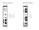
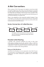
Panel Descriptions
This section explains the basic layout of the front and rear panels of your
new Aviom product. The diagrams on the previous pages can be used
as a quick visual guide to the location of the components of the AV-P2
mentioned in this section.
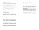
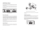
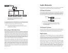
AV-P2 Front Panel
The front panel of the AV-P2 contains the Output Level DIP switches,
Mute switch, A-Net Channel Selector knob, and LED indicators for Stereo
Pair, A-Net Active, and Power.
LEFT
RIGHT
MUTE
CHANNEL
STEREO
PAIR
A-NET
ACTIVE
POWER
AV-P2
OUTPUT LEVELS
1
2
3
4
5
6
7
8
9
10
11
12
13
14
15
16
ON
The AV-P2 front panel interface
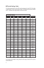
Audio Output Levels
Individual DIP switches are provided for left and right channel audio
output levels. The top of the AV-P2 case includes a handy output level
chart. Move a DIP switch to the up position to activate it.
Mute Switch
The Mute switch provides an easy way to turn the audio output of
the AV-P2 off temporarily without having to change the output level
settings. Use it when making audio connections to other devices,
changing cable routings, etc. Move the switch to the left to mute the
AV-P2 audio output and to the right for normal operation.
A-Net Channel Selector
The AV-P2 can output single channel, dual mono, or stereo audio
signals. The rotary channel selector knob is used to select a mono or
stereo signal from the Pro16 A-Net stream connected to the AV-P2 via
its A-Net In port.
The Channel Selector provides mono or stereo output signals based on
the settings of the Pro16 network’s input module’s Stereo Link switches.
P Note: The left and right audio channels have separate output level
settings. When using mono A-Net channels, this allows two
different output levels to be set if desired.
Stereo Pair LED
The Stereo Pair LED will light whenever the Channel Selector knob is
positioned on either channel that makes up a left/right stereo pair (as
set by the network’s input module).
For example, if A-Net channels 3 and 4 are stereo linked in the network,
moving the AV-P2 Channel Selector knob to either position 3 or 4 will
produce the same result: the Stereo Pair LED will light, A-Net channel
3 is assigned to the AV-P2 left audio output, and A-Net channel 4 is
assigned to the AV-P2 right output.
LEFT
RIGHT
MUTE
CHANNEL
STEREO
PAIR
A-NET
ACTIVE
POWER
AV-P2
OUTPUT LEVELS
1
2
3
4
5
6
7
8
9
10
11
12
13
14
15
16
ON
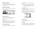
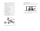
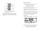
The Stereo Pair, A-Net Active, and Power LED indicators
A-Net Active LED
Whenever a valid A-Net signal is connected to the AV-P2 via the A-Net In
port, the A-Net Active LED will light.
Power LED
The Power LED lights whenever the AV-P2 DC power supply is connected
to a valid AC power source, or when it is receiving power over the
Cat-5 connection. It does not, however, indicate that a valid A-Net digital
stream is being received. That is the job of the A-Net Active LED.