


ENGLISH
XENYX 1204USB/X1204USB User Manual
4
ENGLISH
XENYX 1204USB/X1204USB User Manual
5
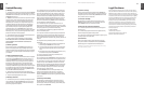
volume in a channel corresponds to the position of the
channel fader. If this were not the case, the eects signal
of the channel would remain audible even when the fader
is turned to zero. When setting up a monitor mix, the aux
sends are generally switched to pre-fader; i.e. they operate
independently of the position of the channel fader.
Both aux sends are mono, are sourced after the equalizer
and oer up to +15 dB gain.
If you press the MUTE/ALT 3-4 switch, aux send ◊
1 is muted, provided that it is switched post-fader.
However, this does not aect the aux send 2 of
the X1204USB.
AUX 1 (MON)
In the X1204USB, aux send 1 can be switched pre-fader and
is thus particularly suitable for setting up monitor mixes.
In the 1204USB, the rst aux send is labeled MON and is
permanently switched pre-fader.
PRE
When the PRE switch is pressed, aux send 1 is sourced
pre-fader.
AUX 2 (FX)
The aux send labeled FX is for sending to eects devices
and is thus set up to be post-fader.
In the X1204USB, the FX send is routed directly to the
built-in eects processor.
If you wish to use the internal eects processor, the ◊
STEREO AUX RETURN 2 connectors should not be
in use.
X1204USB: you can also connect an external eects ◊
processor to aux send 2, however the internal eects
module will be muted.
Routing switch, solo and channel fader2.1.4
PAN
The PAN control determines the position of the channel
signal within the stereo image. This control features a
constant-power characteristic, which means the signal
is always maintained at a constant level, irrespective of
position in the stereo panorama.
MUTE/ALT 3-4
You can use the MUTE/ALT 3-4 switch to divert the channel
from the main mix bus to the Alt 3-4 bus. This mutes the
channel from the main mix.
MUTE-LED
The MUTE LED indicates that the relevant channel is diverted
to the submix (Alt 3-4 bus).
CLIP-LED
The CLIP LED lights up when the input signal is driven
too high. In this case, turn down the GAIN control and,
if necessary, check the setting of the channel EQ.
SOLO
The SOLO switch (X1204USB only) is used to route the
channel signal to the solo bus (Solo In Place) or to the PFL
bus (Pre Fader Listen). This enables you to monitor a channel
signal without aecting the main output signal. The signal
you hear is sourced either before (PFL, mono) or after
(solo, stereo) both the pan control and the channel fader
(see chapter 2.3.6 “Level meters and monitoring”).
The channel fader determines the level of the channel
signal in the main mix (or submix).
Stereo channels2.2
Channel inputs2.2.1
Each stereo channel has two balanced line level inputs on
¼" connectors for left and right channels. If only the
connector marked “L” is used, the channel operates in mono.
Stereo channels are designed to handle typical line level signals.
Both inputs can also be used with unbalanced jacks.
LEVEL
For level matching, the stereo inputs feature a LEVEL switch
which selects between +4 dBu and -10 dBV. At -10 dBV
(home-recording level), the input is more sensitive than at
+4 dBu (studio level).
Fig. 2.4: Panorama and routing controls
Fig. 2.5: Stereo channel inputs and LEVEL switch
Control Elements and 2.
Connectors
This chapter describes the various control elements of your
mixing console. All controls, switches and connectors will be
discussed in detail.
Mono channels2.1
Microphone and line inputs 2.1.1
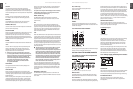
MIC
Each mono input channel oers a balanced microphone
input via the XLR connector and also features switchable
+48 V phantom power supply for condenser microphones.
The XENYX preamps provide undistorted and noise-free gain
as is typically known only from costly outboard preamps.
Please mute your playback system before you activate ◊
the phantom power supply to prevent switch-on
thumps being directed to your loud speakers. Please
also note the instructions in chapter 2.4.2 “Voltage
supply, phantom power and fuse”.
LINE IN
Each mono input also features a balanced line input on a
¼" connector. Unbalanced devices (mono jacks) can also be
connected to these inputs.
Please remember that you can only use either the ◊
microphone or the line input of a channel at any one
time. You can never use both simultaneously!
LOW CUT
The mono channels of the mixing consoles have a
high-slope LOW CUT lter for eliminating unwanted
low-frequency signal components (75 Hz, 18 dB/octave).
GAIN
Use the TRIM control to adjust the input gain. This control
should always be turned fully counterclockwise whenever
you connect or disconnect a signal source to one of the
inputs.
COMPRESSOR
Each mono channel features a built-in compressor which
lowers the dynamic range of the signal and increases its
perceived loudness. The loud peaks are squashed down
and the quiet sections are boosted.
Turn the COMP knob clockwise to add more compression
eect. The adjacent LED with light when the eect is
engaged.
Equalizer2.1.2
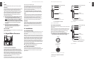
All mono input channels include a 3-band equalizer. All
bands provide boost or cut of up to 15 dB. In the central
position, the equalizer is inactive.
The circuitry of the British EQs is based on the technology
used in the best-known top-of-the-line consoles and
providing a warm sound without any unwanted side eects.
The result are extremely musical equalizers which, unlike
simple equalizers, cause no side eects such as phase
shifting or bandwidth limitation, even with extreme gain
settings of ±15 dB.
The upper (HI) and the lower band (LO) are shelving lters
that increase or decrease all frequencies above or below
their cut-o frequency. The cut-o frequencies of the upper
and lower band are 12 kHz and 80 Hz respectively. The mid
band is congured as a peak lter with a center frequency
of 2.5 kHz.
Aux sends2.1.3
Aux sends take signals via a control from one or more
channels and sum these signals to a so-called bus. This bus
signal is sent to an aux send connector and then routed,
for example, to an active monitor speaker or an external
eects device. The return from an external eect can then be
brought back into the console via the aux return connectors.
For situations which require eects processing, the aux
sends are usually switched post-fader so that the eects
Fig. 2.1: Connectors and controls of mic/line inputs
Fig. 2.2: The equalizer of the input channels
Fig. 2.3: The AUX SEND controls in the channel strips