


ENGLISH
PRO MIXER DX2000USB User Manual
4
ENGLISH
PRO MIXER DX2000USB User Manual
5
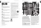
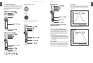
Rack mounting the DX2000USB1.4
Your DX2000USB is shipped with optional rack ears. If you
want to make your DX2000USB a desktop mixer, loosen
the screws from the side panels and remove the rack ears
(note that there is a left and a right one).
Warranty1.5
Please register your mixer on our website at behringer.com
to become eligible for our extended warranty. The serial
number [ 71] can be found on the rear panel.
Packing1.6
Your BEHRINGER PRO MIXER DX2000USB was carefully
packed in the factory and the packaging was designed to
protect the unit from rough handling. Nevertheless, we
recommend that you carefully examine the packaging and
its contents for any signs of physical damage, which may
have occurred in transit.
If the unit is damaged, please do not return it to us, ◊
but notify your dealer and the shipping company
immediately, otherwise claims for damage or
replacement may not be granted. Shipping claims
must be made by the consignee.
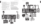
Mono Input Channel2.
Plug a mic or line source (tape, CD player etc.) into the
appropriate MIC [ 52] or LINE [ 51] input. Speak or play music at
typical volume to check out and set up the channel.
Mic and line inputs are on balanced XLR and ◊
¼" jacks respectively. Balanced operation gives
best noise performance. Unbalanced microphones
need to have XLR pins 1 and 3 shorted. Any Line
source will work perfectly well if a mono jack is
used, or the ring and barrel of a TRS jack are shorted
(see chapter 10 “CONNECTIONS”).
Input selection2.1
Inputs are on the back panel. Your input source is selectable
between MIC and LINE by a switch [ 1]. A pair of associated
LEDs [ 2] lets you know which input is selected.
Gain setting2.2
Gain is dependent on EQ. Set up your EQ before ◊
ne-tuning gain. If you re-EQ, also re-check gain.
Quick way2.2.1
Channel input level is continuously monitored by a pair of
LEDs [ 3] . As long as the SIG. LED is flickering and the CLIP is
not, the gain is reasonable. Mic channel input level can be
continuously adjusted by the GAIN knob [ 4] (from +10 to
+60 dB; Mic signals are low, therefore they need to be heavily
pre-amplified).
CLIP lets you know if you overload the channel (it lights
at +18 dB).
SIG. lets you know if a signal is present (it only ◊
responds to bass frequencies). That’s why you can use
it to keep an eye on the beats.
If you are using a mono line source in a mic channel, ◊
the gain structure is comparable to that on a
stereo music channel, albeit 20 dB more sensitive.
(from - 10 to + 40 dB ; = 20 dB pad on mic input)
Gain setting by using PFL 2.2.2
Pre-Fader-Listen is the professional way to set gain. Hit the
PFL button [ 13] to temporarily send the channel signal to
the PFL bargraph meter [ 39] . Adjust the GAIN control until
the bargraph meters are in the yellow (0 dB) but not the
red (Clip). Once gain has been set for a channel, release its
PFL button.
You will usually want to PFL only one channel at a time, ◊
otherwise the PFL meter reading will be meaningless.
Insert point2.3
Situated on the rear of the console, mic channels have insert
points [ 50] on TRS jacks. (These are post-gain and pre-EQ).
You can use these combined input/output sockets to put a
compressor, gate or any other signal processor(s) in line with
your microphone (see chapter 10 “CONNECTIONS”).
Compressors can help even out voice volume, adding ◊
loads of energy, but they can also cause feedback
problems if over-used. Noise gates shut o mics
automatically when not in use—useful for keeping
out music spillage which can muddy the sound of
your mix. Often a compressor/gate combination is
best. Check out the excellent BEHRINGER range of
interactive dynamics products.
Equalizer2.4
The mic channel EQ section comprises three control knobs
and one switch. Depressing the LOW CUT switch [ 5] rolls off
the bass end (-18 dB/oct @ 75 Hz). We recommend using
this feature with microphones to eliminate “popping” and
handling noise. Where loud music is playing, LOW CUT also
helps to avoid bass feedback. Separate controls cut and
boost HIGH [ 6] , MID [ 7] and LOW [ 8] frequencies respectively.
Use EQ creatively to sweeten the sound of your microphone,
or defensively to help cut feedback (see below for
EQ specifications).
EQ Frequency Range Centre
High Shelving EQ 10 kHz +/– 12 dB OFF
Mid Peaking EQ 750Hz +/- 8 dB OFF
Low Sheiving EQ 50Hz +/– 12 dB OFF
Tab. 2.4: Equalizer of the mono input channels
If you are serious about your mic channel, and want ◊
to really kill feedback, you can patch our FEEDBACK
DESTROYER PRO DSP1124P across the channel
insert point at the rear of the console. It is ideal for
this purpose.
Output2.5
Mic channel output is fed directly into the main mix, not
via the X and Y subgroup channels. Level is controlled by a
precision 100 mm fader [ 14] , while stereo position is set by
the PAN control [ 10] . The channel signal is sent to the mix
by depressing the CHANNEL ON switch [ 12] . A LED indicator
illuminates when the channel is on. (Channel on is the
inverse of the more traditional channel mute found on
standard recording consoles).
The mic channels are routed to the RECORD OUT ◊
jacks [ 66] on the rear panel of the DX2000USB, but not
to the LINE OUT jacks [ 22] situated to the left of the
main meters.
The faders used are special high-quality true-log ◊
faders. These give ultra-smooth operation even at
low levels, on par with those used in very expensive
studio consoles.
Effects2.6
You can patch a mono or stereo outboard effects processor
into your DX2000USB via the SEND [ 53] and RETURN [ 54] jacks
on the back panel. Now you can add effects to your voice
instantly simply by punching the illuminated EFFECT button
[ 9] . The effect send level is dependent on the fader setting.
Adjust the desired amount of effect (from -oo to +30 dB) by
the FX RETURN knob [ 42] to the right of the bargraph meters.
Set your eects unit input level so that the input ◊
meter reading (if there is one) is healthy when you are
sending a typical signal to it. Too low a level will mean
too much hiss on your eects return, too high and
you’ll get distortion.
Stereo Input Channel3.
Plug a phono (turntable) or line source (CD player etc.)
into the appropriate PHONO/LINE [ 59] or CD [58] input. Play
music at a typical volume to check out and set up the
channel. Press the PHONO/LINE button if you would like to
use the PHONO/LINE jacks for a line-level source instead of
a turntable.
Input selection3.1
Inputs are on the DX2000USB’s back panel. Your input source
is selectable between a pair of stereo inputs by the INPUT
switch [ 1] at the top of the channel strip. An associated pair of
LEDs [ 2] lets you know which input is selected. The choice of
inputs depends on which of channels 3 - 7 you are looking
at. The mixer is set up as follows:
Channel Input 1 Input 2
3 PHONO/LINE 1 CD 1 / USB
4 PHONO/LINE 2 CD 2
5 PHONO/LINE 3 CD 3
6 LINE 1 CD 4
7 LINE 2 CD 5
Tab. 3.1: Stereo channel configuration
Never patch line level devices into your highly sensitive ◊
phono inputs. Phono cartridge output is measured
in millivolts. Line level signals are of the order of
magnitude of a volt. With line levels you are looking
at a signal up to 100 times more powerful than the
phono pre-amplier is designed to handle! Press the
PHONO/LINE button to allow the PHONO/LINE jacks to
operate at line-level.
If for some reason your turntable has a built-in RIAA ◊
pre-amp, you should patch it into a line level input.
A mix could include three turntables (channels 3 - 5) ◊
and two samplers for creative DJ work, or four CD/cart
players plus a stereo tape recorder for a broadcast
studio. In fact any line level signal could be patched
into any line-level input.
Gain setting3.2
Gain is dependent on EQ. Set up your EQ before ◊
ne-tuning gain.
Quick way 3.2.1
Channel input level is continuously monitored by a pair of
LEDs [ 3] . CLIP lets you know if you’re about to overload the
channel (it lights at +18 dB). The SIG. LED only responds
to bass frequencies and is perfectly suited to keep an eye
on the beats. As long as the signal LED is flashing on the
beat (and the CLIP LED isn’t) you can be sure the gain is
reasonable. Do this for all music channels. Channel gain can
be continuously adjusted by the GAIN knob [ 4] (from -20 to
+20 dB).
If you are in the habit of slamming the channel faders ◊
all the way up (+6 dB), try to keep your MAIN faders
at a compensatory -6 dB to make sure you don’t
risk distortion. At this level PFL and MAIN meters
should show the same level (check this by engaging
PFL on the channel currently playing), allowing
easy comparison between outgoing (playing) and
incoming (cueing) tracks. Keep an eye on the output
meters—red spells trouble. Remember—distortion is
not volume, and any distortion introduced before the
power ampliers and speakers will worsen your sound
and cause amps and speakers to clip sooner.
Gain setting by using PFL3.2.2
Pre-Fader-Listen is the professional way to set gain, and we
always recommend you do it if you have the time. Hit the
PFL button [ 13] to temporarily send the channel signal to the
PFL meter [ 39] . Adjust GAIN until the PFL meter is hitting the
yellow (up to +10 dB) but not the red (clip). Once gain has
been set for a channel, release its PFL button.
Normally you will want to PFL only one channel at a ◊
time. This might not be true if you are layering tracks,
and/or using “Permanent PFL”—see the chapter 7
“HEADPHONES, MONITORS & PFL”. Also note that the
mono PFL meter is a sum of L and R channel signals.