


11 FEEDBACK DESTROYER PRO FBQ2496 User Manual
5.3 FBQ2496 in studio applications
Thanks to the FBQ2496’s exible conguration, it makes perfect sense to use it at
the studio or for home recordings. When in Parametric EQ mode, the FEEDBACK
DESTROYER PRO puts up to 20 fully parametric equalizers per audio channel at
your disposal. Everything is possible: from simple signal processing to total signal
manipulation. For example, you can also use the FBQ2496 to remove distortion
from your studio monitors, or you may use it to aid the EQ function on your
mixing console if it only has semi-parametric EQs.
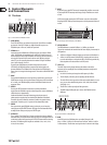
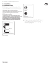
6. Incoming Signal Level
Make sure that the level of the signal being fed into your FBQ2496 is always
correctly set! That way, the FBQ2496 will always be able to eectively suppress
feedback. To correctly set the signal level, use the LEVEL METER display (1).
Theupper clip LEDs should ideally never light up. At any rate, aim to avoid the clip
LEDs constantly being lit up.
If the signal level is too low, the music looses its dynamics, and the result is
a weak, hissing sound that does not set itself through. Similarly, you should
avoid at all cost signal levels that are too high because they will overdrive
the FBQ2496 converters. Digital distortion (unlike its analog counterpart)
isextremely unpleasant because such distortion does not occur gradually but
extremelyabruptly.
7. MIDI control
MIDI stands for “Musical Instrument Digital Interface.” It is a “language” used to
transmit control information between dierent electronic devices: instruments,
PCs, drum computers, eects units, etc. That way, a device’s parameters can be
automatically modied at a previously determined point in time.
To make such communication possible, the following conditions have to be met:
• All devices must be correctly connected to one another.
• One device, called “master,” sends MIDI information via one or several MIDI
channels. The device receiving control information, called “slave,” has to be
set to the correct MIDI channel in order to receive the information.
• The control information being sent has to be “understood” by the MIDI
devices receiving it.
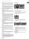
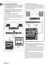
7.1 MIDI connections
The MIDI connectors found on the rear panel are on internationally standardized
5-pin DIN jacks. You need dedicated MIDI cables to connect the FBQ2496 to
other MIDI equipment. Normally, complete cables will be purchased for this use.
MIDIcables should have a maximum length not exceeding 15 meters.
MIDI IN: Receives MIDI control data. The receive channel is determined in the
SETUP menu.
MIDI THRU: Provides an unchanged copy of the signal received at the MIDI IN,
forexample, to daisy-chain several FBQ2496.
MIDI OUT: Transmits MIDI data to a connected computer or other FBQ2496.
Transmitted are program data as well as status information for signal processing.
◊ No loop lines are allowed with MIDI connections, i.e. the master
device can send only control information, and the slave device(s)
can only receive control information–and not the other way around.
Depending on your application, some devices can function both as
masters and slaves.
7.2 Activating and deactivating MIDI
With some applications, having the option to disable the MIDI function of a
device can be useful. This means that the device does not react to the incoming
MIDI control data; instead, it merely passes the incoming MIDI signal through.
The FBQ2496 gives you the option to decide whether it should react to incoming
MIDI control data.
◊ Even when the MIDI function is deactivated on the FBQ2496, the MIDI
signal still passes through the unit and can be tapped into at the MIDI
THRU connector.
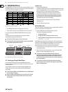
1. Press BANDWIDTH and BYPASS simultaneously. The MIDI menu is activated
if the LEDs on both buttons as well as the MIDI LED under the display
areblinking.
2. Press the BANDWIDTH button; then use the wheel to activate or
deactivateMIDI.
MIDI on: on MIDI o: off
3. Press any button to exit this menu.
7.3 Adjusting a MIDI channel
Using a MIDI channel, a master can transmit 16 dierent data segments, eachone
using its own channel. To make sure a slave only receives the information
intended for it, the corresponding MIDI channels have to be assigned to it rst.
1. Press BANDWIDTH and BYPASS simultaneously. The MIDI menu is activated
if the LEDs on both buttons as well as the MIDI LED under the display
areblinking.
2. Press BANDWIDTH again. Now, a MIDI channel can be selected using the
wheel. The display shows channel numbers as follows: c 1, ... c14, c15, c16.
3. Press any button to exit this menu.
7.4 MIDI controller
Each one of the 16 MIDI channels can transmit a lot of dierent information–
for example, note, keystroke strength and the so-called controllers.
A controller is a command (e.g. instrument, volume, balance, footswitch position)
that in certain situations has to be dened very specically. A total of 128
dierent controllers can be set up. There are several standards (0 = bank select,
7 = main volume) but no xed norm for the assignment of controllers to specic
controller numbers (0 - 127) exists. Dierent MIDI devices may react dierently to
the same controller numbers.
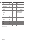
To eectively control your FBQ2496, it is important to know which controller
numbers can inuence individual parameters.