


7 FEEDBACK DESTROYER PRO FBQ2496 User Manual
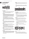
(11) PEQ
After keeping the PEQ button pressed for a few moments (the LED on the
PEQ button blinks), use the wheel to set the number of parametric lters.
Theystart with the lter number 20 and can go down to lter number 1,
stepy step (see g. 4.2). At the same time, the already set Single-Shot lters
are shown.
If you only briey press the PEQ button (the LED on the PEQ button is lit),
anylter can be called up using the wheel. The number of the selected lter
is shown in the display, and the corresponding lter LED blinks. Amplication,
bandwidth and mid frequency parameters can now beshown.
◊ Only the parameters of the parametric filters can be manually
adjusted! The settings of the Single-Shot filters and the automatic
filters can be shown but not modified.
(12) FREQUENCY
When the FBQ2496 is in the PEQ mode (the LED on the PEQ button is lit),
the mid frequency of each individual lter can be set. To modify the mid
frequency, press the FREQUENCY button. The frequency range can vary from
20 Hz to 20 kHz.
(13) LEFT-RIGHT
The LEFT-RIGHT button lets you select the channels you wish to edit. If your
FBQ2496 is in the stereo mode, both channels are automatically selected and
both LEDs are lit. In this mode, you only have to set the parameters for one
channel, and they are automatically carried over onto the other channel.
If you keep the LEFT-RIGHT button pressed for a few moments, the two
channels are separated from one another. That way, you can assign dierent
parameters to each of the two channels. Toggling between the two channels
is done by briey pressing the LEFT-RIGHT button.
Keeping the LEFT-RIGHT button pressed for a few moments restores the
stereo coupling, and the settings from the active channel are automatically
carried over onto the other channel.
◊ Whether your FBQ2496 is running in mono or in stereo is stored each
time you turn the unit off, and the same mode is reloaded each time
you power up the unit.
(14) BANDWIDTH
Use the BANDWIDTH button to set the bandwidth (Q-factor/quality) of the
selected parametric lter. The adjustable lter quality encompasses a range
from 1/60th of an octave up to 10 octaves. The FBQ2496 has to be in PEQ
mode (the LED on the PEQ button is lit).
(15) BYPASS
Keeping the BYPASS button pressed for a few moments activates the hard bypass.
The unit’s input is directly routed to the output and the lters arebypassed.
◊ Please use the BYPASS function with extreme caution because
deactivating the filters gives free reign to unsuppressed feedback.
(16) MIDI
Simultaneously pressing BANDWIDTH and BYPASS gets you into the MIDI menu
(both button LEDs are lit). Here you can activate and deactivate MIDI and select a
MIDI channel (ch. 7).
(17) WHEEL
WHEEL is a continuous rotary control. Use it to make adjustments to the
selected parameter. Turn the wheel clockwise to increase parameter values.
Turn it counterclockwise to lower the parameter values.
(18) POWER
Press POWER to turn on your FEEDBACK DESTROYER PRO.
◊ Attention: The POWER switch does not fully disconnect the unit from the
mains. To disconnect the unit from the mains, pull out the main cord plug
or appliance coupler. When installing the product, ensure the plug or
appliance coupler is readily operable. Unplug the power cord completely
when the unit is not used for prolonged periods of time.
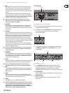
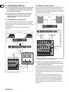
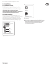
3.2 The rear
(19)
(20)
Fig.3.4: Mains connector, fuse switch and serial number
(19) The mains connection is established using a cable with an IEC mains connector.
An appropriate mains cable is included.
(20) You can replace fuses at the FUSE SWITCH of the FBQ2496. Always replace
fuses with the same type. Please follow the instructions given in
chapter 9 “SPECIFICATIONS.”
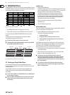
(21)
Fig. 3.5: FBQ2496’s MIDI connections jacks
(21) The FBQ2496 features a complete set of MIDI functions. In addition to the
usual MIDI IN and MIDI OUT ports, the MIDI THRU allows you to loop
through MIDI data.
(22)
(24) (23)
Fig. 3.6: FBQ2496’s rear connections
(22) Use the OPERATING LEVEL switch to change from home recording
level (-10 dBV) to studio level (+4 dBu), and vice versa. The level meters
are adapted automatically to the selected nominal level, so that the
FEEDBACKDESTROYER PRO will always work in its optimum operating range.
(23) INPUT LEFT/RIGHT
These are the balanced inputs of your FBQ2496. They are laid out as ¼" TRS
and XLR connectors.
(24) OUTPUT LEFT/RIGHT
Both of the FBQ2496 outputs are also laid out as balanced ¼" TRS and
XLRconnectors.