


13 FEEDBACK DESTROYER PRO FBQ2496 User Manual
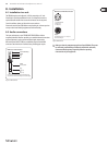
8. Installation
8.1 Installation in a rack
The FBQ2496 requires one height unit (1 HE) for mounting in a 19" rack.
Pleasekeep in mind that an additional 10cm (4") of depth in the back are
required to enable trouble-free access to the connectors on the rear panel.
For rack installation, please use M6 machine screws and nuts.
Please make sure that your FBQ2496 has enough cooling air, and never put it on
an amp or other heat-emitting equipment to avoid overheating.
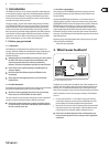
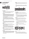
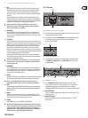
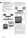
8.2 Audio connections
The inputs and outputs on your FEEDBACK DESTROYER PRO are laid out
completely balanced. Whenever possible, try to establish balanced connections
to other equipment in order to maximize disturb signal compensation.
MIDI connections (IN/OUT/THRU) are established using the standard DIN
connectors. Data transmission is achieved using a oating opto-coupler.
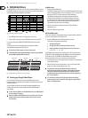
strain relief clamp
sleeve
ring
tip
sleeve
ground/shield
For connection of balanced and unbalanced plugs,
ring and sleeve have to be bridged at the stereo plug.
Balanced ¼" TRS connector
ring
cold (-ve)
tip
hot (+ve)
Fig. 8.1: ¼" TRS connector
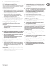
output
For unbalanced use, pin 1 and pin 3
have to be bridged
1 = ground/shield
2 = hot (+ve)
3 = cold (-ve)
input
12
3
1
2
3
Balanced use with XLR connectors
Fig. 8.2: XLR connector
◊ Make sure that only competent people install your FBQ2496. They must
be sufficiently earthed during and after the installation; otherwise,
electrostatic discharges may negatively affect the operating
characteristics of your equipment.