


20
EURODESK MX3282A
8.4 Desk Normalization
All board settings should be set to the normal default condition before or after every session. Usually faders are
set to zero (minus infinity) EQs set flat, trimpots and channel aux sends turned fully anticlockwise etc. Many
controls have a natural initial setting. For EQ cut and boost this is unity gain. However, some settings, such as
selecting pre or post for channel aux sends, will depend on the operating environment (e.g. studio or live), or on
a particular engineers preferred way of working.
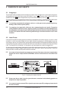
9. PATCHBAY
A patchbay allows to patch the audio signals of most components in your studio from a central point and send
them to other units, which makes your entire cabling better structured and is indispensable for professional
work. If you want to use your studio as effectively as possible then it is preferable to use a complete patchbay
wiring scheme. But even smaller studio configurations will benefit from less sophisticated patchbay solutions.
The majority of commercially available patchbays include two rows with 24 phone jacks each in a 19" 1 U rack
panel. On the rear, either a corresponding number of phone jacks or contacts for soldering signal leads can be
found. Each group of four of these phone jacks forms one module. The configuration of some Patchbays can be
changed by inserting jumpers or turning individual modules.
With the help of our ULTRAPATCH PRO PX2000, an easy-to-use 24-patchbay offering phone jacks throughout,
you can easily understand the four different modes. With the ULTRAPATCH PRO you can select between the
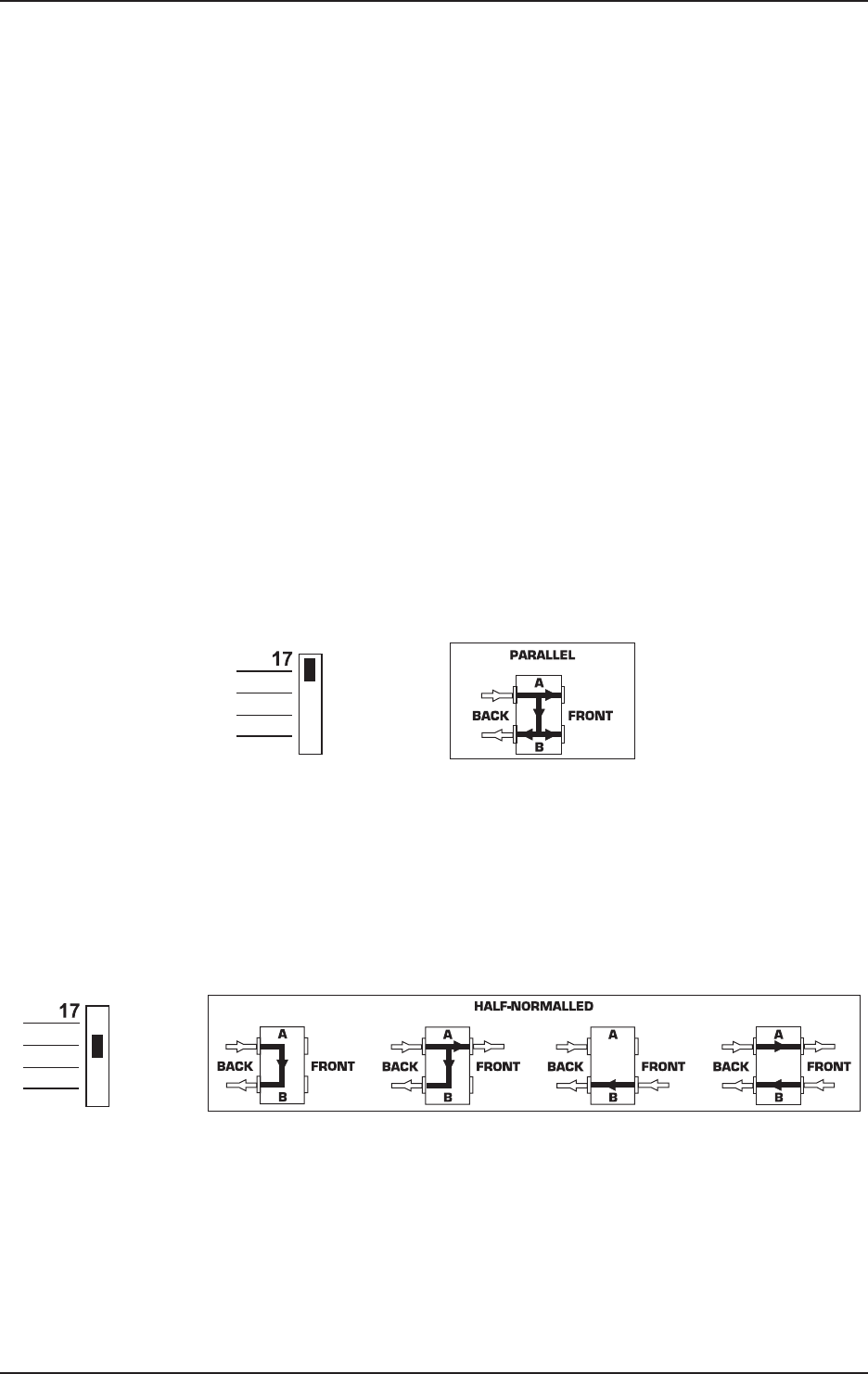
four different operating modes simply by setting a switch on the upper panel (example: module 17):
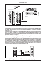
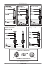
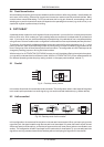
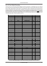
9.1 Parallel
Fig. 9.1: Patchbay mode parallel
In this mode, all terminals of one module are interconnected. This configuration doesnt make sense at first glance
but is used to split up and send one audio signal (e.g. aux send) to several destinations (e.g. effects devices).
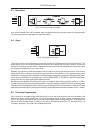
9.2 Half-normalled
Fig. 9.2: Patchbay mode half-normalled
In this configuration, the contacts of the two jacks on the rear are interconnected. When you insert a plug into the
upper front jack, the signal routed through the rear path is not interrupted. Only when the lower front jack is used
will the rear panel route be split up, so that the two upper and the two lower phone jacks are connected to one
another. This configuration is called input break and is used mainly for insert paths. So you can easily patch the
signal from a mixing console channel at the Patchbay without interrupting the signal flow in the channel.
9. PATCHBAY