


EURODESK SX4882
Input/output conguration 23
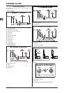
In a quadrophonic setup MIX-B should be kept separate +
from the main mix (S48 UP).
OK: This example has been extreme. Chances are if you were
touring with the sort of PA / multitrack described above you'd also
have a massive FOH console, separate foldback mixer, and a rider
that would make Bill Graham blanche. None of the applications
examples are designed to be used as a BLUEPRINT. Rather,
they should give you some idea of the scope and exibility of your
EURODESK SX4882. Use your imagination to nd novel ways of
solving problems and creating extra facilities.
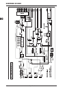
Expanding the EURODESK19.
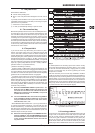
Connections19.1
The EXPANDER PORT is input only, and provides access to all but
the PFL/SOLO buses. Since the nominal internal operating level
of your EURODESK SX4882 is 0 dB, and that at the jack outputs
+4 dB, the sends from the outputs of console 2 must be attenuated
by +4 dB if unity gain between it and the primary console is to be
maintained. Wiring is as follows:
EURODESK 2 > -4 dB > EURODESK 1
Subgroup outputs
1 to 8
EXPANDER PORT sub-
group inputs 1 to 8
Aux outputs 1 to 6
EXPANDER PORT aux
inputs 1 to 6
Main mix output
EXPANDER PORT main
mix inputs
MIX-B output
EXPANDER PORT MIX-B
input
Another manufac-
turer’s desk
> -X dB > EURODESK 1
Subgroup outputs
1 to 8
EXPANDER PORT sub-
group inputs 1 to 8
Aux outputs 1 to 6
EXPANDER PORT aux
inputs 1 to 6
Main mix output
EXPANDER PORT main
mix inputs
MIX-B output
EXPANDER PORT MIX-B
input
Alignment19.2
To nd out the value of “X” align the consoles in the following way.
Patch a 1 kHz sine tone (or play a sustained B above middle C
on a keyboard) into a channel on each console. Set up each con-
sole so that the signal produces unity gain (0 dB) at every output
(use each console's PFL or equivalent function to do this). Now,
connect the outputs of the second console into the EURODESK
EXPANDER PORT. Mute the channel on the EURODESK carrying
the signal, and look at the EURODESK outputs. Systematically
adjust the reading on each bus until they all read 0 dB by adjusting
the master send levels of console 2 (i.e.: master aux send controls,
main mix master faders, subgroup faders, etc.).
Timecode20.
In analog multitrack recording timecode usually goes down on the
edge of the tape: track 8, 16 or 24, with the adjacent track left clear
(GUARD BAND) to stop bleeding between recorded tracks and
code. Digital formats do not waste any audio tracks on timecode:
a separate sync is provided.
Ideally, timecode should be patched from the multitrack out directly
into the synchronizer input. Normally, a 24 track tape is striped with
timecode before a session commences. Any sequenced music,
click track, mix automation is then referenced to it.
Always check sync before laying down any sequenced music:
record a click track, then check to see that a “live” playback
doesn't drift. Timecode comes in various formats. The general
rule is: format (and make/model) of timecode generator must be
matched to the reader. This shouldn't be a problem if recording
and mixing take place in-house and under one roof. It's when
tapes move around that problems arise (be sure to include every
conceivable technical detail on a tracksheet accompanying the
master tape). Fortunately, there are ways to generate fresh in-sync
timecode even where none existed in the rst place, otherwise
most remixes would never happen. You would rather not have
to, though, since it takes time, effort, and an intelligent “learning”
synchronizer to do it.
If the gain from the recorder is too low to drive the sync unit,
re-stripe at a higher level or =
amplify the recorded timecode somehow, possibly via a desk =
channel not routed to any of the main buses. In this case use
the channel's direct out to drive the synchronizer's input, in
order to keep the timecode as remote as possible from the
audio (timecode crosses over like nothing else we know).
Bouncing21.
Sometimes you want to play back from one or more tracks, route
the signals to a new track or pair of tracks, and re-record. This
process is commonly referred to as bouncing. Examples would
be when reducing 4 lead vocal take tracks down to 1, reducing
4 separate tom-tom tracks down to a stereo pair via noise gates,
putting a wild effect or EQ onto a dry signal, “comping” backing
vocal tracks, etc.
On an analog tape recorder, bouncing to an adjacent track is to be
avoided. A feedback loop can be set up, since for all overdubs or
bounces you will be using the same (sync) head for both playback
and record. Organize your track layout so that any bounces you
might have to do are always over at least one track.
There are no restrictions when using digital multitracks.
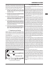
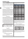
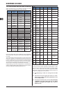
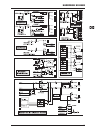
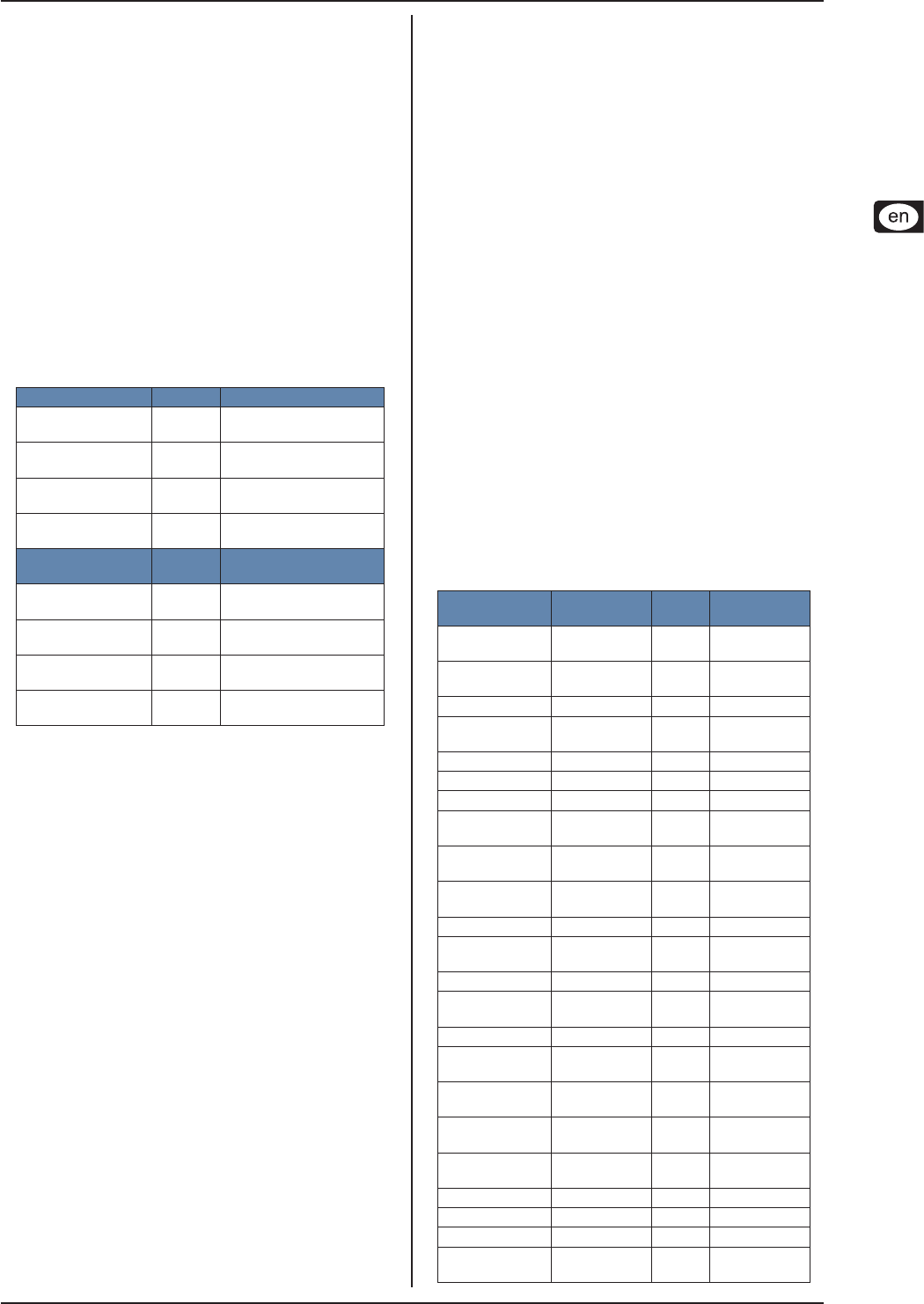
Input/output conguration22.
Nominal level
Bal-
anced
Attenuation
EURODESK
internal
+4 dBu - -
XLR microphone
input
- Yes
Trimpot / PAD
switch
Line A input +4 dBu Yes Trimpot
Line B / tape
input
+4 dBu /
-10 dBV
Yes Gain switch
Aux sends +4 dBu No Pot
Aux returns 0 dBu No Pot
MIX-B output +4 dBu No Pot
Subgroup output
+4 dBu /
-10 dBV
Yes Gain switch
Main mix 1/4"
jack
+4 dBu No Fader
Main mix XLR
+4 dBu (max.
+28 dBu)
Yes Fader
2-track out RCA +4 dBu No Fader
2-track in 1/4"
jack / RCA
+4 dBu No No
External input +4 dBu No No
Channel insert
out
+4 dBu No No
Channel insert in +4 dBu No No
Channel direct
out
+4 dBu No Fader
Subgroup insert
out
0 dBu No No
Subgroup insert
in
0 dBu No No
Main mix insert
out
0 dBu No No
Main mix insert in 0 dBu No No
Control room out +4 dBu No Pot
Studio out +4 dBu No Pot
Meter / analyzer
out
+4 dBu No No