


11
EUROLIGHT LC2412
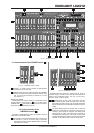
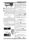
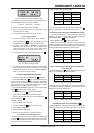
Fig. 2.11: Serial number and mains connector
SERIAL NUMBER. Please take a few minutes and send to
us a completely filled out warranty card within 14 days of
the original date of purchase. Otherwise, warranty claims
may be rendered invalid. Or will out the warranty
information online at www.behringer.com.
FUSE COMPARTMENT / VOLTAGE SELECTION. Before
connecting the unit to a power outlet, please make sure
that the selected voltage matches your local voltage. When
replacing fuses, please make sure that you always use
fuses of the same type. Some units allow for switching
between 230 V und 120 V. Please note: when connecting
a unit intended for the European market to a 120 V power
outlet, you must also replace the factory fuse with a higher-
value fuse.
Power is supplied via an IEC connector. The matching
cable is provided with the unit.
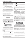
3. PRESETS
This chapter describes individual steps used to set up, recall
and fade in/out presets (pre-determined lighting situations). Even
though your LC2412 can execute complex functions, its controls
are easy to master, provided you invest some time to familiarize
yourself with the way they work. To familiarize you with the
control elements and their functions step by step, let us begin
with setting up presets (preset = the total collection of all fader
positions of the A PRESET section at one particular time). Lets
start with 12 channels first.
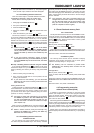
All statements referring to channels 1 - 12 apply also to
channels 13 - 24 (upper mode).
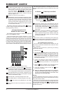
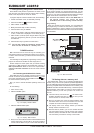
+ Think of presets as building blocks used to create
more complex lighting situations: memories
capture the setup of a preset (up to 24 channels) on
one fader; chases use presets (level step) as well
as memories (memory step) as single steps.
Fig. 3.1: Using presets and memories
3.1 Basic configuration
Pull all the faders all the way down to the zero mark. This way,
you assure that you start your exploration of the possibilities of
the LC2412 from a neutral setting, and can observe the results
of the changes you implement directly. Use the POWER switch
to power up your BEHRINGER EUROLIGHT LC2412. The LC2412
displays now the setup that was most recently used, just prior
to being powered down last time.
If you want to start completely from the beginning, you can
use a key combination to erase all programmed
configurations. More on this subject in chapter 7.8.
3.1.1 Preset mode
To work exclusively with presets, you have to first switch into
preset mode. Select P in the bank display accordingly.
1. Press the UP or DOWN keys repeatedly until P is shown in
the display. The display flashes for roughly 3 seconds.
2. Once the flashing stops, your LC2412 is in preset mode. The
CHANNEL FLASH function is now automatically activated,
which is also shown by the lit control LED (CH FLASH ).
3. Raise the MAIN fader as well as Fader A .
4. You can now use faders 1 - 12 of the A PRESET section to
create a stage design. The illumination level of individual
lighting elements can be read out on the control LEDs, aligned
next to the FLASH keys.
+ You can not program or recal memories while in
preset mode. On the other hand, stored chases
can be recalled whle in preset mode.
3.2 Expanding to 24 preset channels
(upper mode)
All operations applicable to channels 1-12 can be executed on
channels 13 - 24, once you switch into upper mode.
1. Press the UPPER switch .
The control LED indicates that the LC2412 is now in upper
mode, that is, that the faders of the A PRESET section now
control channels 13 - 24. The faders from the B MEMORY
section affect channels 13 - 24 while in preset mode.
2. Set up your preset by moving the faders of the A PRESET
section into the desired position.
In case you had already executed setups to channels 13 -
24, you have to first put the faders into the previously
selected position before being able to again align these
channels.
3. To quit upper mode, simply press the switch.
+ After switching over, the control LEDs indicate the
illumination condition of the respective active
channels independent of the position of the faders.
To alter the setting of a channel, you have to first
bring the respective fader into the previous
position.
Additional features:
While in upper mode, the FLASH keys fade in the channels
13 - 24.
3.3 Crossfading between presets
To crossfade between two presets, you need an additional
preset. This additional preset is created by utilizing the faders in
the B MEMORY section.
1. Pull the fader B upward, the fader A downward.
The MAIN fader remains open.
3. PRESETS