


7
EUROLIGHT LC2412
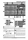
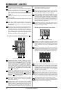
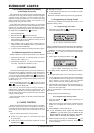
2.1 Control elements of the A PRESET section
Fig. 2.2: A PRESET section (detail)
Faders 1-12. Used to set the intensity of light elements
connected to the dimmer pack.
UPPER switch. When you press this switch, the A PRESET
section is switched to the twelve additional channels. After
that, you can set up the intensity of channels 13 - 24. See
also chapter 3.2.
Setting up presets
Channel faders are used for setting up a preset that can be
directly recalled by moving fader A . As in all other setups,
the MAIN fader (see chapter 2.6) determines the maximum
illumination level of selected light sources.
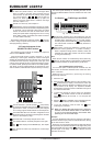
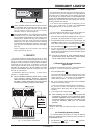
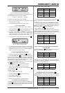
2.2 Control elements of the
B MEMORY section
The faders of the B MEMORY section are located in the block
underneath the A PRESET section.
These faders control the illumination level of an entire group
of channels in a ratio to one another that you previously
determined by setting up the A PRESET faders and saving
this setting as a memory.
Fig. 2.3: B MEMORY section
Exception: When the LC2412 is in preset mode (P shown in
the bank display), the faders control the same channels as the
faders of the A PRESET section. This way, you can simul-
taneously create a second preset.
- These faders are also a part of this section, but they
have a double function. When the LC2412 is in sound to
light mode (party light function), they control the illumination
level of individual memories assigned to particular frequency
ranges.
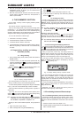
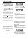
The BANK display shows the storage bank to which the
memories you recall belong. It also shows if the LC2412 is
currently in preset mode (P diplayed). The display starts
flashing when you switch into preset mode, and lights up
constantly after three seconds. The preset mode is active
only after the flashing has stopped. This prevents accidental
activation of the preset mode as well as rough fades.
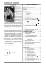
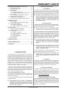
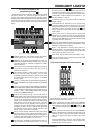
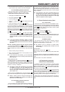
Fig. 2.1: Section overview
2. CONTROL ELEMENTS