


21
EUROLIGHT LC2412
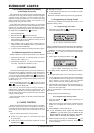
9.1 Cables recommended for DMX512
The cables should be manufactured according to EIA-485 or
EIA-422 specifications. Using shielded, twisted, double-stranded
data transmission cables is recommended. For example, these
are the same cables used for transmitting digital audio data in the
AES/EBU format. You can also implement lines with a second
wire set, used as a replacement in case of a malfunction.
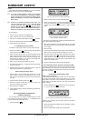
Using high-quality mic cables is also possible, but their length
shold be limited to 500 m due to the high cable capacity near a
data line.
9.2 Terminal resistor (bus termination)
Using a termnal resistor at the end of the line is an additional
condition needed for glitch-free data transmission. To this end, a
120-Ohm resistor is located between both conductors (Pin 2 and
Pin 3) in an extra connector. Connect this connector to the DMX
out connector of the last piece of equipment in the DMX chain.
Shorter connections (up to several meters/roughly 15 ft) do
require termination.
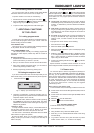
9.3 Pin assignment
9.3.1 DMX512 connections
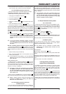
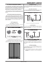
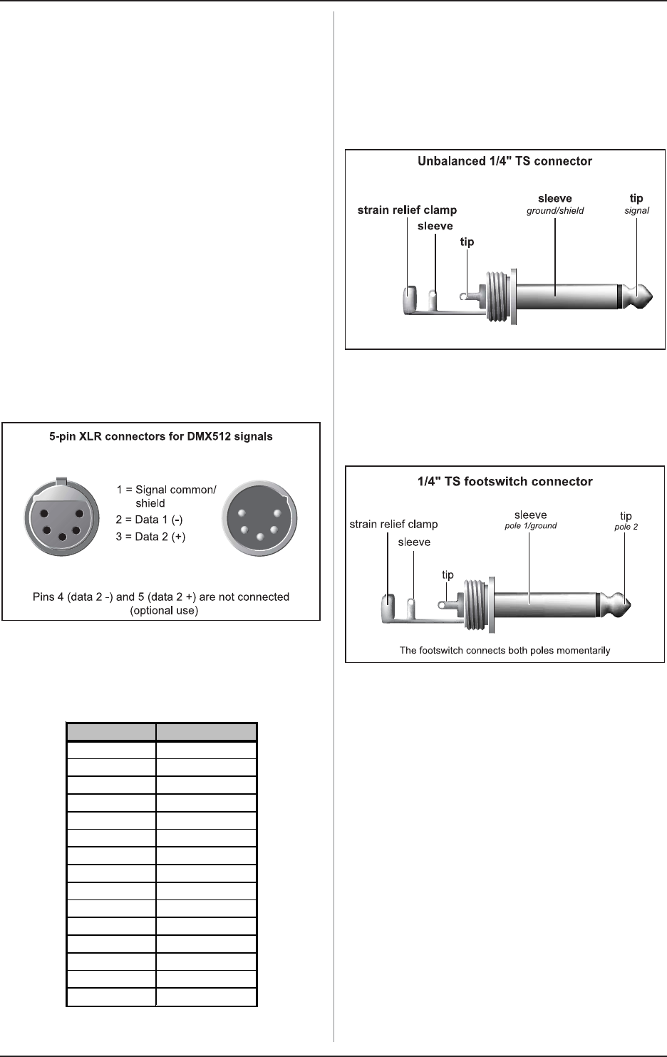
The DMX512 norm mandates the use of 5-prong XLR
connectors. The correct layout is shown in fig. 9.1.
Fig. 9.1: 5-prong XLR connector for DMX512 connections
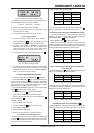
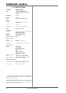
9.3.2 Sub D connections (analog control)
The following table shows the cable layout of the individual
contacts of the sub D connection for analog dimmer control.
Pin No. Cons. channe
l
Pin 1 Channel 1
Pin 2 Channel 2
Pin 3 Channel 3
Pin 4 Channel 4
Pin 5 Channel 5
Pin 6 Channel 6
Pin 7 Channel 7
Pin 8 Channel 8
Pin 9 Channel 9
Pin 10 Channel 10
Pin 11 Channel 11
Pin 12 Channel 12
Pin 13 Special 1
Pin 14 Special 2
Pin 15 Ground
Table. 9.1: Cable layout of the sub D connection
9.3.3 MIDI connection
Coonect to other MIDI equipment or another EUROLIGHT LC2412
by using common MIDI cables. The cables should never be longer
than 15 m (45 ft).
9.3.4 Audio connections
To control the EUROLIGHT LC2412 via an audio signal, please
use a mono jack connector with standard configuration.
Fig. 9.2: 1/4" TS connector for audio signals
9.3.5 Footswitch
You can use a footswitch to trigger chase steps. This way,
both of your hands remain free, letting you control additional
settings of your LC2412.
Fig. 9.3: Footswitch connector
As long as a footswitch is kept pressed, the connection of
both contacts is closed. Therefore, a footswitch does not act as
a switch.
9.4 Rack mounting
Your EUROLIGHT LC2412 is factory-equipped with rack-
mounting brackets. You can screw these on to the side of your
LC2412 on a per-need basis.
+ Always make sure that your LC2412 is provided
with sufficient ventilation to avoid overheating of
the unit!
9. INSTALLATION