


13
ULTRAMATCH PRO SRC2496
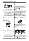
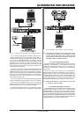
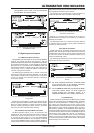
+ When using the XLR connectors in an unbalanced
configuration, pins 1 and 3 on the connectors
inserted must be interconnected!
Fig. 5.1: Unbalanced transmission to the ULTRAMATCH PRO
Fig. 5.2: Unbalanced transmission from the
ULTRAMATCHPRO
5.3 Digital inputs and outputs
5.3.1 Balanced XLR connection
The digital XLR inputs and outputs are not bound by the AES/EBU
protocol. They accept and deliver data streams in both the
professional and the consumer format. Should the RCA input already
be occupied by another device, it is even possible to connect the
RCA output of, say, a CD player to the ULTRAMATCHPRO XLR
input by using an adapter. To do this, you will need a cable such as
the one shown in fig. 5.2, except that instead of a female XLR
connector, a plug must be mounted.
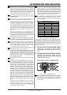
The following figure illustrates how to correctly connect the
balanced input and output connectors. Basically, it is the same
wiring scheme normally used for balanced audio connections
such as, for example, the connection between a microphone
and a mixing console.
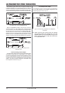
Fig. 5.3: Connecting the ULTRAMATCH PRO in a balanced
configuration
Selecting the correct cable is not critical. For distances of less
than 20 m, generally available microphone cables have no negative
effect. For greater distances or higher requirements (mobile
operation, powerful high-frequency fields), however, you should
use special 110-Ohm cable with double shielding.
5.3.2 Unbalanced coaxial RCA connection
The RCA inputs and outputs, in turn, are not bound to the
S/PDIF format. They accept and deliver data streams in both the
professional and the consumer format. It is even possible
to connect the XLR output (e.g. from the BEHRINGER
ULTRA-CURVE PRO DSP8024 or other equipment) to the RCA
input on the ULTRAMATCH PRO by using an adapter. Whether or
not the reverse will work, namely connecting the ULTRAMATCH
PROs RCA connector to the XLR input of another unit, depends
on the sensitivity of the XLR input in question.
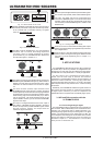
The following figure illustrates the correct connection for
unbalanced input and output connections via RCA plugs.
Fig. 5.4: Connecting the ULTRAMATCH PRO in an
unbalanced configuration
Basically, it is the same wiring scheme as is the norm for
unbalanced audio connections in hi-fi systems, e.g. between a
CD player and amplifier.
For distances less than 10 m, standard coaxial line cable has
no negative influence. However, should greater distances be
involved, you should use XLR.
5.3.3 Optical connection
Toslink optical inputs and outputs are also not bound by the
S/PDIF format. They accept and deliver data streams in both the
professional and the consumer format. Optical connections are
by nature not sensitive to electric interference fields, easy to
cable and astonishingly robust.
The following figure illustrates how to correctly connect the
optical input and output connections.
Fig. 5.5: Connecting the ULTRAMATCH PRO optically via
Toslink
+ For many consumer devices the consumer format
at the optical input is an absolute necessity,
otherwise they do not accept the signal.
+ The ULTRAMATCH PRO does not support the ADAT
®
multi-track format, which can thus neither be
looped through nor converted. (ADAT
®
is a
registered trademark of the Alesis Corporation)
5.3.4 Wordclock
Feeding a wordclock signal into the rear BNC connector enables
external synchronization of the ULTRAMATCH PRO. Wordclock
signals are normally distributed in a network configuration, i.e.
are relayed and terminated with 75-Ohm coaxial cable,
BNC-T adapters and terminating resistors. Commercially available
BNC cables are usually used as connecting cables. In order to
offer maximum flexibility, the ULTRAMATCHPROs BNC input
has a high-impedance design and is not equipped with an internal
75-Ohm terminating resistor. Should the ULTRAMATCHPRO be
the last device in the signal chain, however, it is necessary to
put a T-connector into the BNC connector. A 75-Ohm terminating
resistor (in the form of a short BNC plug) goes on one end of the
T-connector and the BNC cable from the master delivering the
wordclock signal on the other end.
5. INSTALLATION