


8
ULTRAMATCH PRO SRC2496
3. APPLICATIONS
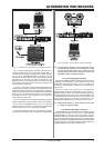
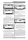
Fig. 2.7: Serial number on the cover
SERIAL NUMBER. Please take the time to fill out and return
the warranty card within 14 days after the date of purchase,
so as to benefit from our extended warranty. Or register
online at www.behringer.com.
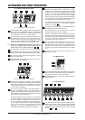
Fig. 2.8: Wordclock connector
The BNC connector WORDCLOCK is a high-impedance
connector with no internal terminating impedance
(75 Ohms). Use it to connect equipment for external
synchronization of your ULTRAMATCHPRO. Please note
the instructions given in chapter 3.2.3.
Fig. 2.9: Digital outputs
The digital XLR output is the standard output connector for
AES/EBU signals (AES/EBU LED lights up). When S/PDIF is
selected, the XLR output also provides this signal. Further
information on these connectors can be found in chapter
5.3.
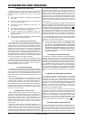
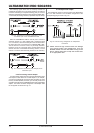
This is the OPTICAL (Toslink) output connector of the
ULTRAMATCHPRO. When the unit is shipped, the optical
Toslink input/output connectors have dummy plugs attached
to protect them from dirt and to prevent the emission of light.
These dummy plugs can be removed easily if you wish to
use the connectors. The digital standard format for this
output is S/PDIF. However, you can also transmit AES/EBU
signals via this output.
RCA output. The digital standard format for this output is
also S/PDIF. If AES/EBU has been selected in the output
section, this output also provides AES/EBU signals. Unlike
the XLR connector, however, this output allows for
unbalanced signal transmission.
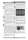
Fig. 2.10: Digital inputs
- DIGITAL INPUTS.
The RCA input is the digital standard input for S/PDIF signals.
The OPTICAL input (Toslink) is also used for S/PDIF signals.
XLR input. The digital XLR input is the standard input
connector for AES/EBU signals. It can also be used to feed
in S/PDIF signals, like the RCA and OPTICAL inputs which
can be used to process AES/EBU signals in addition to the
S/PDIF format.
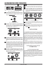
Fig. 2.11: Analog outputs and inputs
ANALOG OUTPUTS. These balanced analog XLR outputs
(stereo) provide the analog signal generated by conversion
from a digital format.
ANALOG INPUTS. Use these balanced analog XLR inputs
(stereo) to feed in analog line level signals. Please note the
instructions on level adjustment given in chapter 2.1.1
(section ).
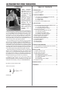
3. APPLICATIONS
Your ULTRAMATCH PRO will soon prove to be a practical tool
of valuable help in almost any situation. Its straightforward user
interface is fun to work with. Dont be misled by the plain design:
the SRC2496 is a really flexible tool in a variety of applications.
You dont need to own a professional recording studio to
benefit from the wide range of features and functions
implemented in the SRC2496. Problems with the interfacing of
optical and coaxial connectors, removing copy protect bits,
converting sampling rates from 48 to 44.1 or 32 kHzall of these
tasks are quite common daily routines even in a home recording
environment.
Additionally, the ULTRAMATCHPRO is the logical choice as a
high-end A/D and D/A converter or enhanced source selector
for digital inputswhenever you need an inexpensive and
reliable alternative to equipment with considerably higher prices.
3.1 A/D and D/A conversion with the
ULTRAMATCH PRO
3.1.1 Converting analog to digital
The ULTRAMATCH PRO is equipped with high-grade A/D and
D/A converters. With the SRC2496 you own an excellent tool for
preparing your analog audio data for digital processing or for
converting analog signals directly and storing them on a digital
medium. The analog input is set for studio levels (+4 dBu), but
can be adapted to low-level signals with the GAIN control. Please
use the level meter to adapt the level of the input signal, as
described in chapter 2.1.1. The illustrations 3.1 and 3.2 below
show you how to connect the unit.