


6
ULTRAMATCH PRO SRC2496
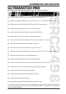
2. CONTROL ELEMENTS
2.1.1 Monitor and input sections
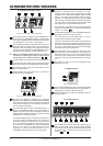
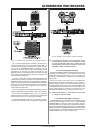
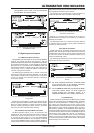
Fig. 2.2: Input section control elements
Use the GAIN control to adapt the signal level perfectly to
the circuitry of your ULTRAMATCH PRO. The level should
be as high as possible, but the 0 dB LED should only light
up occasionally or never at all to avoid distortion.
The PHONES control governs the headphone volume. You
can monitor either the analog output or input by setting the
SOURCE switch accordingly. The analog output always
provides the signal applied to the selected digital input, so
this signal can be monitored with the headphones, too.
+ When the ULTRAMATCH PRO operates as an A/D-D/A
converter, the digital input signal is applied to the
analog output only in DIG IN mode (see , ).
This is the stereo 1/4" TRS connector for your headphones.
The ANALOG IN and/or ANALOG OUT LEDs indicate which
signal (input or output) is being displayed by the level meter.
The SOURCE switch routes the analog input or output
signal to the level meter.
LEVEL METER. The signal shown here can always be
monitored with the headphones.
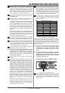
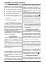
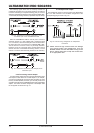
Fig. 2.3: Input section control elements
This LED array displays the sampling rate of the digital
input signal. One LED lights up constantly when the sampling
rate is kept accurately or does not deviate from the nominal
value by more than approx. 2 kHz. Otherwise, the LED for
the next value starts flashing.
The LOCK LED lights up when a valid digital signalto
which the ULTRAMATCH PRO can be synchronizedis
applied to the active input. When digital input signals are
being processed, this LED should be on all the time, showing
the presence of a stable input signal.
The ERROR LED warns you of erroneous (or the absence
of any) input signals. It displays various error modes, such
as Unlock, Parity Error, Bi-Phase Error and Confidence
Error. The signal is then checked as to whether or not it is
an audio signal. Any detected error makes the SRC2496
mute all of its outputs to protect down-stream audio
equipment. As long as the ERROR LED is lit, the
ULTRAMATCH PRO cannot process any input signals.
The EMPH LED shows you whether or not the input signal
includes an emphasis marker. Emphasis is a high-
frequency boost function that is applied during the digital
recording but is undone during playback. When the LED
lights up, the signal was emphasis-processed during
recording. You should always make sure that the EMPH
LEDs in the input and output sections read the same status.
The COPY LED (= copyright) lights up when the input signal
was supplied from a copy-protected data carrier.
The ORIG LED (= original) informs you that the audio signal
received is an original signal, i.e. that it can be copied (see
chapter 2.1.3, section ).
The AES/EBU LED lights up when an AES/EBU signal has
been applied at the active input connector.
The same holds true for the S/PDIF LED, i.e. when a
consumer-format signal has been applied.
If the unit is set to A/D and D/A converter mode, the S/PDIF
LED lights up even when no digital signal is present. This is
due to the circuitry used and does not indicate a malfunction
of the unit. Further information on the formats AES/EBU
and S/PDIF can be found in chapter 4.2.
Use the SOURCE switch to select the active input. Only
one digital input can be activated at a time. However, in
A/D-D/A converter mode, you can use one digital input and
the analog inputs simultaneously (parallel A/D and D/A
conversion). For further information please refer to chapter
3.1.3.
The LEDs XLR, RCA and OPTICAL indicate the input
activated by the user.
2.1.2 Mode section
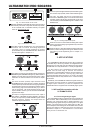
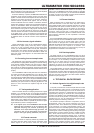
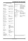
Fig. 2.4: Mode section
The two LEDs SAMPLE RATE CONV and A/D & D/A CONV
inform you about the operating mode of your SRC2496, i.e.
sampling rate converter or A/D-D/A converter.
Use the MODE switch to switch over between these two
operating modes.
2.1.3 Output section
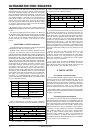
Fig. 2.5: Output section
The SAMPLE RATE switch selects the sampling rate to
which the input signal is to be converted or made available
at the outputs. For this purpose, the SRC2496 must be set
to internal mode, i.e. it has to function as a master unit (see
sections and ).